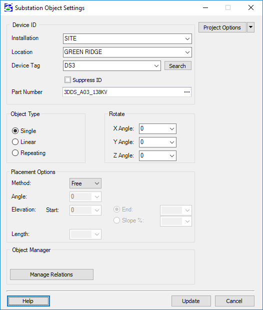
Substation Object Settings Dialog
Displays when you click the Symbol Settings button from the Insert Substation Object dialog while working in the 3D Layout mode. The dialog enables you to specify additional object settings before placing the device.
If working in any other mode other than 3D Layout mode, this dialog is not displayed.
After selecting a part number to place from the Insert Substation Object command, click the Symbol Settings button to display the following dialog. The software displays the Substation Object Settings dialog if the current drawing mode is 3D Layout. This dialog enables you to specify additional object settings before placing the device.
| Setting | Description |
|---|---|
| Device ID | The Device ID group-box contains controls to comprise the ID of the device. A combination of the Installation, Location, and Device Tag creates the unique ID of the device. |
| Installation | The first part of a device ID which is used to uniquely identify a device in the project. The installation name is the highest level designation and most commonly used to identify any major part of plant, site, or equipment. |
| Location | The second part of a device ID which is used to uniquely identify a device in the project. The location name is most commonly used to identify a specific area or assembly within the installation. |
| Device Tag | The third part of a device ID which is used to uniquely identify a device in the project. The device tag is typically comprised of a Tag Mnemonic such as FU for a fuse and a sequential number or page and line number reference. The format of the device tag is user definable in the project options. |
| Suppress ID | Enable this option to hide the Device ID in the graphics. |
| Part Number | Displays the part number for the object. If you are not placing a symbol by part number, then this field will be empty. You can click the ellipsis (...) button next to the field to display the Select Part Number dialog where you can assign a part number for the symbol. |
| Object Type |
Single: A single substation device such as a structure or piece of equipment. These parts are designated with a value of SGL in the Part_Type field of the parts database. Linear: An object whose size and shape is dynamic. A cable would be a common variable object as its length and sag can vary depending on distance and other factors. These parts are designated with a value of VAR in the Part_Type field of the parts database. Repeating: Similar to a variable object except that the object is inserted as many times as needed to span the distance specified by the user rather than being stretched like a variable object. A fence would be a common repeating object because you would want to insert multiple sections of the fence and have the part number quantified for the total number of sections placed. These parts are designated with a value of REP in the Part_Type field of the parts database. |
| Rotate | Specify rotation angles in the X,Y, or Z directions in the provided fields. You can enter in a specific angle or select from the list of default angles (0,90,180,270) |
| Method |
Select a placement method to assist in placing the object in the correct position. You can select from the following choices:
|
| Angle | This setting is only enabled when you set your method to cable and is typically used to change the angle of an object you place on a cable such as a clamp. |
| Elevation |
Specifies the Elevation (variable objects only) to set a depth relative the DTM or Project Reference Point. |
| Length | Sets a fixed length to variable objects. |
| Auto apply relations | If a device is placed in the 3D model using the Hook method and the hooked object is in an Object Manager group, the placed device will be inserted into the same group if this option is enabled. |
| Manage Relations | Displays the Substation Objects Manager, which enables you to manage all devices placed in the current 3D model. |
| Project Options |
Opens the project options dialog so you can adjust your project settings as desired. Clicking the down arrow gives you the following choices:
|
| OK | Places a new device, based on the dialog control values, in the 3D model. The device placement routine is based on the selected Method. |
| Cancel | Cancels the placement of the symbol or macro. |