| Create Graphical Plan
|
-
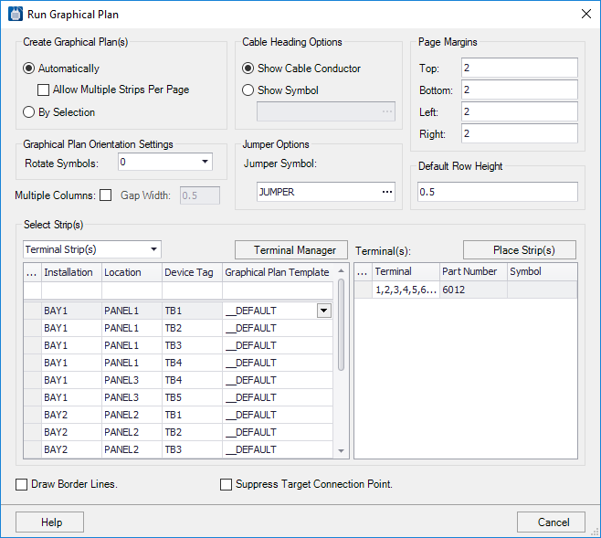
Automatically: Select this option if
you wish the software to place strips on a page. If you create the graphical
plans automatically you can select the
Allow Multiple Strips Per Page check box
to allow multiple strips on a single page if they fit.
-
By Selection: Select this option if
you wish to select a position for the terminal strip on the page that is
currently open.
|
| Graphical Plan Orientation Settings
|
-
Rotate Symbols: In this field you can
enter a rotation value so that the terminal strip or other symbol will run
either vertically or horizontally.
-
Multiple Columns: Select this check
box if you wish the software to place more than one terminal strip on a page in
side-by-side columns. The software will only do this if there is sufficient
room on the page. Use the
Gap Width field to set the space
between columns.
|
| Cable Heading Options
|
-
Show Cable Conductor: Select this
option you want a cable connection to be indicated by the conductor color.
-
Show Symbol: Select this option if
you want a cable connection to be indicated by a symbol such as an X. The
symbol CROSS is included in the catalog for this purpose.
|
| Jumper Options
|
Use the
Jumper Symbol field to select a symbol
that will represent a jumper connection in the graphical plan. The symbol
JUMPER is included in the symbol catalog for this purpose.
|
| Page Margins
|
In this part of the dialog you can define margins
for the graphical plan page.
|
| Default Row Height
|
You can enter a default height value for table rows.
|
| Select Strip(s)
|
Select the strips that you wish to include in the
graphical plan in the
Select Strip(s) area of the dialog. In
the
Graphical Plan Template column you can
select the template to use for the selected strip.
Note: The first row
of the grid is an auto-filter row which makes it easier to find specific
terminal strips in the list.
|
| Terminal Manager
|
Click to display the
Terminal/Pin-Plug
Manager.
|
| Suppress Target Connection Point
|
Select this check box if you wish to omit the
connection point from the from/to target information in the graphical plan.
|
| Place Strip(s)
|
When you click the Place Strips button, one of two
scenarios happen:
-
If you selected the
Automatic method of generating the
graphical plan, the
New Page dialog will appear. Enter a drawing set,
installation, location and page number for the first page that will be created
for the graphical plan. If additional pages are required they will follow the
first page. You can also select a title block, page format and make other
settings for these pages.
Select
OK in the
New Page dialog to generate the graphical plan. You can
view the plan by opening the pages that are created.
- If you selected the
By Selection method of generating the
graphical plan you will not see the
New Page dialog. You will go to the currently open page and
will be prompted on the command line to select an insertion point.
Select a point on the page that will be the
upper left corner of the graphical plan for the strip. The strip will be placed
on the page and the software will return to the
Run Graphical Plan dialog, allowing
you to select the next strip.
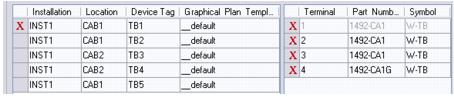
When you return to the
Run Graphical Plan dialog, strips and
terminals that have been placed in a drawing are marked with a red X mark.
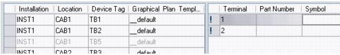
If terminals are marked with an exclamation point (
! ), it indicates that no part number has been assigned to the terminal symbol.
You can click inside the
Part Number field to get a
Browse button that will take you to the
Part Number Assignment dialog. A part
number (with wiring diagram symbol) is required to ensure proper generation of
the graphical plan.
|
 The Run Graphical Plan dialog
lets the user automatically create drawing pages showing a representation of
selected terminal strips.
The Run Graphical Plan dialog
lets the user automatically create drawing pages showing a representation of
selected terminal strips.