Routing Options Dialog
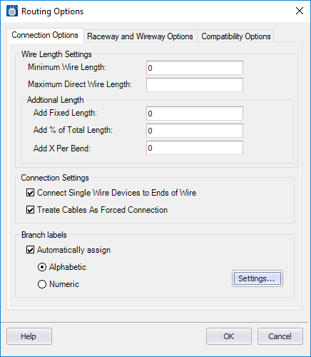
This dialog lets you make additional settings for the shortest distance routing function.
Accessed when:
- You press the Routing Options button in the Shortest Distance Routing dialog.
| Setting | Description |
|---|---|
| Minimum Wire Length | The value entered in this field sets the minimum wire length. If the Shortest Distance Routing function calculates any wires to be shorter than this value, the minimum length will then be assigned. |
| Maximum Direct Wire Length | If you have defined that a connection point should be wired direct rather than going through a wireway, but the direct wire length distance ends up being larger than the Maximum Direct Wire Length value entered here, then the program will route the connection through wireways even though it is marked as direct. |
| Additional Length | This area contains two fields to enter values for
additional wire length. If the wire length calculated by the Shortest Distance
Routing function will be used for wire cutting, you may wish to add such an
additional length to every wire to ensure there will be sufficient wire to
reach the device.
Use the Add Fixed Length field to add an absolute value or the Add % of Total Length field to add a percentage of the total wire length. You can enter values in both fields. If you enter values in both fields, the program will add both additional lengths to the total length of the wire. This allows you, for example, to use a percentage adder to compensate for the amount of winding and turning a wire does inside a wire duct while the absolute value is for connection-based compensation such as strip length or bending radiuses. When you enter a percentage value, enter it as a decimal fraction, not a whole number (for example, enter 0.10 not 10%). |
| Connection Settings | If you select the
Connect Single Wire Devices to Ends of Wire
check box, devices that have connection points that can only accept one wire
are connected at the beginning or end of a daisy chain.
Note: You can create
single wire connections in the
Wiring Manager or in the
Parts Database in the
Single_Wire_Connection field.
|
| Treat Cables as Forced Connection | When selected you can represent a wire harness in your schematics by placing a cable symbol on each wire that is a part of a harness. Before running shortest distance, you can select this check box and the shortest distance program will treat every cable connection as a forced connection to ensure that the routing is done properly for the harnesses. |
| Branch Labels |
Select the Automatically Assign check box to assign branch labels to each branch of a wire in the shortest distance wiring list. These labels do not appear in the schematic. Select either the Alphabetic or Numeric options to set the format of the branch label, either Alphabetic (A, B, C...) or Numeric (1, 2, 3...). Select the Settings button to display the Automatically Assign Branch Label dialog where you can define additional branch label settings. |
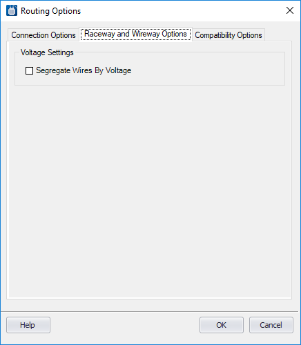
Raceway and Wireway Options Tab
| Setting | Description |
|---|---|
| Segregate Wires By Voltage | Select if you wish wires with different voltage ranges to be routed through separate wireways. |
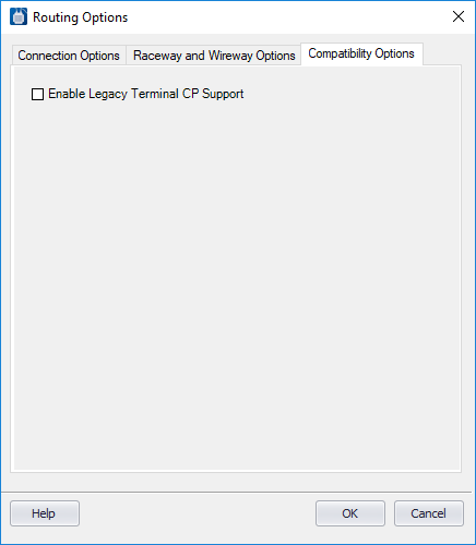
Compatibility Options Tab
| Setting | Description |
|---|---|
| Enable Legacy Terminal CP Support |
Select this option if you are using a legacy project. In these projects, connection points for terminals were identified as a combination of terminal number and then the Internal (I) or External (E) designation. For example, the external connection point of terminal TB2-1 would be "1E". In current versions of the software, this combination is not necessary. |
When finished defining the settings in the Routing Options dialog, select the OK button to load your settings.