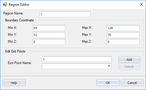
Region Editor Dialog
The dialog provides fields so you can define or edit regions on a Panel Layout Drawing. A region typically represents a single panel. You might have one region for the items mounted on the door and another region for the items mounted on the back panel; therefore, by defining regions you are telling the software which items are on the same panel.
Accessed when:
- Select Insert Region
- Select Edit Region
| Setting | Description |
|---|---|
| Region Name | Enter an identifying name for this region in the Region Name field. |
| Boundary Coordinate | In the Boundary Coordinates area of the dialog, the X and Y coordinates you selected for the region will be displayed. If desired, you can change these values as well as entering Z coordinate values. |
| Edit Exit Points |
An exit point is where the wires will enter or leave the panel. The Exit Point Name field prompts the name of the next exit point that will be placed. This is a sequential name; the default first exit point name is 1. You can change this to another number or to a letter if you prefer. The exit points you have defined will be listed in the drop-down list below the Exit Point Name field. |
| Add | To define exit points, select the Add button. The Region Editor will close and you can select one or more exit points on the panel drawing for the current region. These points will be marked by a red circle with cross inside. Press the <Enter> key or right click to return to the Region Editor. |
| Delete | You can delete an exit point by selecting it from the list and then selecting the Delete button. |