3D Substation Settings
Lets you define and save Project/User Settings for the project database.
Accessed when you access the Backpage menu by selecting the File option from the ribbon.
Project Settings
The Project Settings tab provides fields which affect all project database settings.

| Setting | Description |
|---|---|
| Profile |
You can save your customized settings to a profile if you commonly have different settings depending on the project. Profiles make it easy to quickly switch between different commonly used settings without needing to individually each time. |
| BOM and Labels |
BOMBalloonTemplateName? Defines the default template to be used when generating an Output Balloon BOM from the 3D Layout Design taskbar. The list is filtered by templates created as Bill of Materials (Construction) reports in the Report Template Designer, and are stored in the ...\Configuration\WorkSpaces\<Workspace>\Standards\Substation\Templates\Reports\ directory. BOMLabelToolTemplateName: You can select from the pull-down the report template that you want the software's construction labels' "Output BOM" command to use when it creates a bill of material report on the drawing based on the labels you added to your construction drawing. (maybe we can link to the label tool topic here) |
| Grounding Grid |
Bullet Radius: If you do not define a specific symbol to use for the grounding grid weld joints, then a default bullet symbol (a circle) is used. This option defines the radius of that bullet symbol. Color: Enter the color number from the Settings>Color Table that corresponds to the color you would like to apply to the grounding grid wires when a new grounding grid is drawn. LevelName: Enter the name of the level that you would like the grounding grid to be drawn on. LineStyle: Enter the line style number that corresponds to the line style you want to apply to the grounding grid wires when a new grounding grid is drawn. LineWeight: Enter the line weight number that corresponds to the line weight you want to apply to the grounding grid wires when a new grounding grid is drawn. PartTypeForGndRod: the software should filter upon in the parts database to identify grounding rods when drawing a new grounding grid. This controls the content of the Ground Rod pull-down list in the Place Grounding Grid dialog. The software reads the 3D_Layout_Symbol field in the part record to identify what symbol to place for the grounding rod. PartTypeForTerminator: Enter the part type value that the software should filter upon in the parts database to identify grounding grid connectors when drawing a new grounding grid. This controls the content of the ??. The software reads the 3D_Layout_Symbol field in the part record to identify what symbol to place for the grounding grid connector. PartTypeForWeldingGndRod: Enter the part type value that the software should filter upon in the parts database to identify grounding rod connectors when drawing a new grounding grid. This controls the content of the Ground Rod Connector pull-down list in the Place Grounding Grid dialog. The software reads the 3D_Layout_Symbol field in the part record to identify what symbol to place for the grounding rod connector. PartTypeForWeldingT: Enter the part type value that the software should filter upon in the parts database to identify a Welding T when drawing a new grounding grid. This controls the content of the Connector 3-wire pull-down list in the Place Grounding Grid dialog. The software reads the 3D_Layout_Symbol field in the part record to identify what symbol to place for the grounding rod connector. PartTypeForWeldingX: Enter the part type value that the software should filter upon in the parts database to identify a Welding X when drawing a new grounding grid. This controls the content of the Connector 4-wire pull-down list in the Place Grounding Grid dialog. The software reads the 3D_Layout_Symbol field in the part record to identify what symbol to place for the grounding rod connector. |
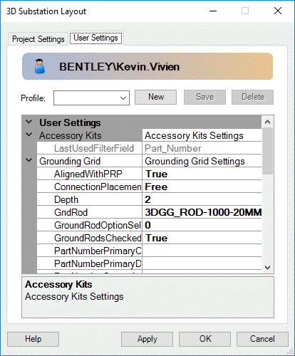
User Settings
The fields in the User Settings tab only affect the current user.
| Setting | Description |
|---|---|
| Profile |
You can save your customized settings to a profile if you commonly have different settings depending on the project. Profiles make it easy to quickly switch between different commonly used settings without needing to individually each time. |
| Accessory Kits | LastUsedFilterField: Displays the last field you filtered on when searching for a part number in the Accessory Kit Manager. This is Read Only. |
| Grounding Grid |
AlignedWithPRP: Defines the default behavior to automatically align Ground Grid placement with the Project Reference Point. ConnectionPlacementMethod: Defines the default placement method
the Grounding Grid tool defaults to for making connections when you first open
the dialog. You can choose between these options:
Depth: Defines the default depth the Grounding Grid tool defaults to when you first open the dialog. GndRod: Enter the default part number of the grounding rod that the software should load in the Place Grounding Grid dialog. GroundRodOptionsSelectedIndex: GroundRodsChecked: This setting controls the default state of the 'Include Ground Rods' toggle in the place grounding grid dialog. Set this to true to have the toggle checked by default. PartNumberPrimaryColName: Defines the column name in the part database that defines the primary Part Number value. If you want to use a description or catalog number field instead of the part number field as the last combo box search field in the Insert 3D Object dialog, you can enter the name of the parts database field here. Note: If you leave
this setting blank, Substation defaults to using the part_number field from the
parts database.
PartNumberPrimaryDescr: Defines the description of the primary Part Number value you specified in the PartNumberPrimaryColName setting. The description you enter would appear to the left of the last combo box search field in the Insert 3D Object dialog. Note: If you leave
this setting blank, Substation defaults to using Part Number as the description
text.
PartNumberSecondaryColName: Defines the column name in the part database whose value you want displayed below the selected part number in the Insert 3D Object dialog. Note: If you leave
this setting blank, Substation defaults to using the Detailed_Description1
field from the parts database.
PartNumberSecondaryDescr: Defines the description of the Secondary Part Number value you specified in the PartNumberSecondaryColName setting. The description you enter would appear to the left of the parts database value in the Insert 3D Object dialog. Note: If you leave
this setting blank, Substation defaults to using Description as the description
text.
PlacementMethod: Defines the default placement method the
Grounding Grid tool defaults to for placing a grounding grid when you first
open the dialog. You can choose between these options:
SpacingX: Defines the default spacing between the grid wires in the X direction the Grounding Grid tool defaults to when you first open the dialog. SpacingY: Defines the default spacing between the grid wires in the Y direction the Grounding Grid tool defaults to when you first open the dialog. TerminatorType: Defines the default Terminator type the Grounding Grid tool defaults to when you first open the dialog. WeldingGndRod: Enter the default part number of the grounding rod connector that the software should load in the Place Grounding Grid dialog. WeldingT: Defines the default Welding (T) connection the Grounding Grid tool defaults to when you first open the dialog. WeldingX: Defines the default Welding (X) connection the Grounding Grid tool defaults to when you first open the dialog. WireType: Defines the default Wire Type the Grounding Grid tool defaults to when you first open the dialog. |
| Object Manager Settings |
AutoApplyHookPointFilter: When set to True, the hook point filter will automatically be set to the last part number that was placed. HookPointSnapDistance: Defines the snap distance for Hook
Points.
|
| Reference Point Settings |
LineColor: Defines the line color for the Reference point. LineStyle: Defines the line style for the Reference point. LineWeight: Defines the line weight for the Reference point. UseActiveSettings: Defines whether to use the active graphic settings when placing the Reference point. |