Place Named Boundary by Civil Cross Section

Workflow
- Access or reference your geometry, terrain and corridor along with other desired files.
- Enable both a 2D and a 3D view.
- Graphically ID the horizontal geometry in the 2D view.
- Select the Drawing Seed.
- Set the scale and the Start and Stop station values.
- Modify other fields and toggles as needed.
- Enable the Create Drawing toggle.
- Data point in the 2D view to place boundaries, then another data point to Accept.
- Select OK on the Create Drawing dialog.
| Setting | Description |
|---|---|
| Drawing Seed | Specifies the drawing seed that sets default values for all of the values on the dialog except the start and stop locations. Also contains definitions for what seed files are used to create the cross sections drawing and seed models including how the drawings are positioned on the sheets. |
| Detail Scale | Sets the scale at which the named boundary will be placed. |
| Name | Enter name of the named boundary. |
| Description | Enter brief description for the new group. |
| Group | Selects the named boundary group. You can also create a new group by selecting New from the drop-down. |
| Name | Enter name of the new group. |
| Description | Enter brief description for the new group. |
| Start Location | Sets the begin station. |
| Stop Location | Sets the stop station. |
| Length | (Available only when By Length is selected) Sets the length, along the path element, of the named boundary element. Also determines the location, along the path, of subsequent boundary elements. If you use the Measure Distance tool next to the field the measured distance displays in the Length field. |
| Left Offset | (Available only when By Length is selected) Sets the distance from left of the path. If you use the Measure Distance tool next to the field, the measured distance displays in the Left Offset field. |
| Right Offset | (Available only when By Length is selected) Sets the distance from right of the path. If you use the Measure Distance tool next to the field, the measured distance displays in the Right Offset field. |
| Interval | Specifies the spacing between consecutive cross sections. |
| Vertical Exaggeration | Specifies the vertical exaggeration for displayed cross sections. Values greater than 1.0 for this parameter increase the exaggeration. |
| Top Clearance | Enables the top clearance to enter a value. |
| Bottom Clearance | Enables the bottom clearance to enter a value. |
| Elevation Datum Spacing | When a profile is shifted, the starting elevation will always be a multiple of this value. |
| Event Point List | It allows you to include an event point list in the Named group. |
| Named Group |
It allows you to create a group of elements like points, cells, drainage nodes, soil borings, and so on. |
| Include Event Points Only | Adds Horizontal and Vertical Event points. |
| Include Named Groups Points Only | It allows you to include only the named group locations. |
| Include Control Points | Adds cross sections at horizontal control points such as PC and PT. |
| Backward Facing | When toggled on, the named boundary is created from
right to left instead of left to right. This causes a cut view that faces the
descending direction of the alignment.
It will be possible to open files created in 10.08.00.88 in this version and vice versa. The Backward Facing attribute will be true on named boundaries that are created with the Backward Facing option toggled on. It will be false otherwise. |
| Create Drawing | When enabled, the process to create the cross section sheets is automatically started after the named boundaries are created. When disabled, the named boundaries are created but the sheets are not created. |
| Show Dialog | When enabled, a dialog with additional parameters set by the Drawing Seed is shown. |
Cross Section Boundaries at Soil Boring Locations & Other Civil Element Locations.
The "Include Named Group Points Only" option is added to the XS Named Boundaries tool.
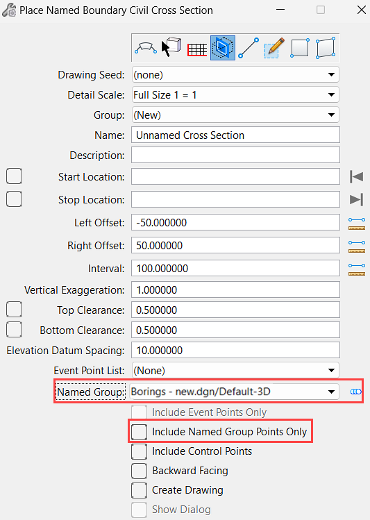
Named Group
Named Groups allow you to create a group of elements (points, cells, drainage nodes, soil borings, etc.). These groups can reside in the active file or any reference file. This option reads all available Named Groups and allows the user to select one from the pull-down. The point locations will be read from the selected Named Group.
When this option is Enabled, XS locations are determined from the point elements within the selected Named Group.
- If a point element in the Named Group is 3D, then the elevation of that element will be used to determine the depth of the Named Boundary at that location.
- If a point element in the Named Group is 2D, then the elevation of that element will not be used to determine the depth of the Named Boundary.
Include Named Group Points Only
- Option is Not Enabled: If this option is not enabled, then the selected Named Group (if any) will be included along with any other specified XS locations.
- Option is Enabled: If enabled, then ONLY the Named Group locations will be placed.
Open Named Group Dialog (Icon)
To facilitate easier access to the Named Groups dialog, we have added the icon as shown below.
