Terrain Model Create Tools
The Terrain Model Create tool group contains tools to create a terrain model from graphical elements, ASCII files, point clouds, LandXML, and importing from various Bentley Civil products. Tools are also supported to merge together two or more models, and to clip models.
Terrain Models can be created from a variety of source data. Each data type has different input requirements, but many options are the same throughout the create tools. Two concepts are utilized in several create tools:
Geographical Coordinate Systems
The Geographical Coordinate Systems section enables the user to covert the data from one coordinate to another "on-the-fly" while processing the data for other tasks. If the data is in the coordinate system needed for downstream tasks, then this section is not utilized. However, if the downstream tasks require a different coordinate system than the source data, the user can select the system of the source data, and specify the system of the create terrain model. Source data from different coordinate systems can be converted during creation, then merged in the Complex Terrain or Merging tool. If the Source and Target are set to None, the source data is assumed to be the design file working units. If the software can detect the coordinate system, it is populated into the Source field.
|
Settings |
Description |
|
Source |
None - specifies the incoming Geographical Coordinate System. displays the Image Projection dialog to select from a searchable library. |
|
Target |
None - specifies the outgoing Geographical Coordinate System. displays the Image Projection dialog to select from a searchable library. |
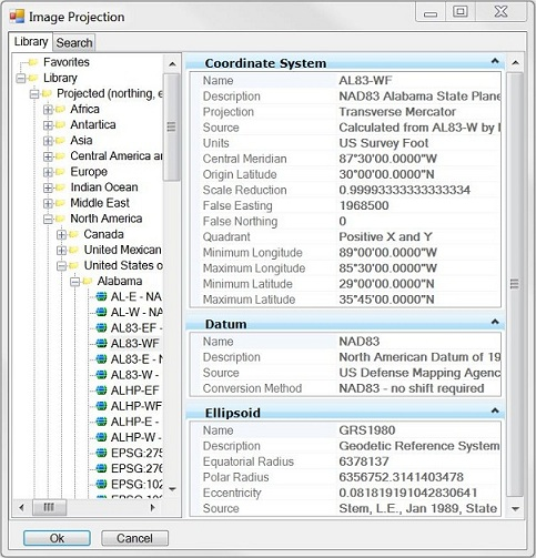
Image Projection
To Select a Geographic Coordinate System from the Library:
- Click the button in the source or target field within the GCS section.
Specifies input coordinate system for incoming data and the output coordinate system relative to the actual coordinate system that is used in the TM.
The secondary Image Projection dialog displays when you select the browse button of the GCS dialog section on the main dialog Create Terrain from File or Create Terrain Model from ACSII.
The Select Geographic Coordinate System dialog opens.
- Expand the Library and double-click a GCS.
or
Select a GCS and click OK.
Specifies input coordinate system for incoming data and the output coordinate system relative to the actual coordinate system that is used in the TM.
This secondary Image Projection dialog displays when you select the browse button on the Geographic Coordinate System dialog section on the main dialog Create Terrain from File, or Create Terrain Model from ASCII.
Workflow
- Select the input coordinate system datum and click OK.
The Projection Settings dialog populates with the selected coordinate system datum.
- Select the output coordinate system datum and click OK.
Filtering
Three options are supported: None, Tile, and Tin. From empirical studies, the tiling algorithm is faster and typically produces a 30% to 50% reduction in file size. The TIN algorithm typically produces a 70% to 90% reduction.
The tiling algorithm is a recursive divide and conquer algorithm that divides the data set into tiles. A best fit plane is calculated for each tile and LIDAR points are removed if they fall within the user set Z tolerance to the plane.
The TIN algorithm filters points if they fall within the user set Z tolerance of the triangle planes. The TIN algorithm first tiles the points into tiles with a maximum of 2 million points and then repetitively triangulates each tile filtering out points.
Once the filtering is complete, the Point Features Before Filter, After Filter, and Percentage Reduction are displayed in the dialog (read-only). If multiple data files are loaded the test filter results are applicable only to the active selection.
Once the option is selected, the input fields change to reflect the selection. Fields common to all options are listed below.
|
Test Filter |
Once the filter fields are populated, check Test Filter to commence the filter routines are populate the Report fields. The fields can be adjusted and processed again (if desired) before the data is imported as a surface. |
|
Source File Units |
If the software can determine the units from the data file, this field is populated. If it cannot determine the units, Unknown is displayed. The user can specify Unknown, Millimeters, Centimeters, Meters, Kilometers, Inches, Feet, US Survey Feet, Miles. If Unknown, then the design file units are used. |
None
No filter is applied if None is selected. No additional inputs are required.
Tile
The tiling algorithm is a recursive divide and conquer algorithm that divides the data set into tiles. A best fit plane is calculated for each tile and points are removed if they fall within the user set Z tolerance to the plane.
|
Z Tolerance |
The variation in the Z coordinate that the surface is allowed to move during the filtering process. Typically for the first invocation of the filtering function, the Z tolerance should be set from 0.5 to 1.0 for imperial data sets and from 0.25 to 0.5 for metric data sets. Depending on the outcome and desired result, the Z tolerance can be varied up or down. |
|
Minimum Tile Points |
A tile will not be subdivided if it has less than this number of points. Typically set this to five. |
|
Max Tile Divisions |
Allowable level of recursion allowed and is the number of times the initial tiling set can be subdivided. Typically set this to five. |
|
Start Tile Length |
The data set is initially divided into tiles of this size, prior to recursion to the minimum tile points. The setting of this parameter requires some knowledge of the distance between the points, which requires an inspection of the points in MicroStation to determine. Typically set this to 10 times the distance between the points. |
Tin
The TIN algorithm filters points if they fall within the user set Z tolerance of the triangle planes. The TIN algorithm first tiles the points into tiles with a maximum of 2 million points and then repetitively triangulates each tile filtering out points.
|
Z Tolerance |
The variation in the Z coordinate that the surface is allowed to move during the filtering process. Typically for the first invocation of the filtering function, the Z tolerance should be set from 0.5 to 1.0 for imperial data sets and from 0.25 to 0.5 for metric data sets. Depending on the outcome and desired result, the Z tolerance can be varied up or down. |
|
Granularity |
Course - Filters more points with some blurring of ridges and valleys. Fine - Filters fewer points with less blurring of ridges and valleys. |
|
Reinsert Points |
After filtering the points a further check is made based on the tolerances and points falling outside the tolerances are reinserted back into the surface. |