Aquaplaning dialog

| Settings | Description |
|---|---|
|
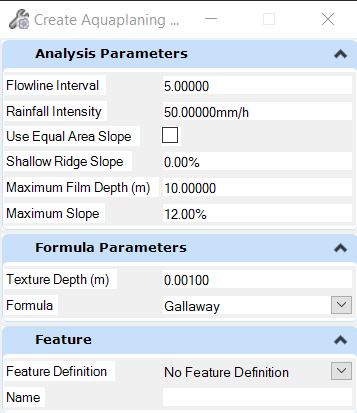
Formula Parameters |
|
|
Texture Depth |
The road surface texture depth (varies on material). |
|
Formula |
Gallaway - formula used to assess aquaplaning risk. Road Research Laboratory - formula used to assess aquaplaning risk. |
| Settings | Description |
|---|---|
| Analysis Parameters | |
|
Flowline Interval |
Default is 500mm, 2 feet. |
|
Rainfall Intensity |
Default is 50mm/hr, 2 inches/hr. |
|
Use Equal Area Slope |
Controls how slopes across the road surface are measured. |
|
Shallow Ridge Slope |
Defines the difference in slope between adjacent triangles on either side of a ridge line, below which the ridge is considered to be shallow. This affects how the flow lines are created. |
|
Maximum Film Depth |
Sets a Maximum Film Depth acceptable value. |
|
Maximum Slope |
Sets a Maximum Slope acceptable value. |
| Settings | Description |
|---|---|
| Feature | |
|
Feature Definition |
Choose the feature definition that describes the element being created. |
|
Name |
The name is populated from the feature definition selected. Override this with a new name if needed. |
Shallow Ridge Slope
Shallow ridges can be created when superelevation reverses, or rolls over, along a road. The Aquaplaning tool creates flow lines, and a ridge will cause two flow lines to be created - one on either side of the ridge. This can cause undesirable results, as shown below:

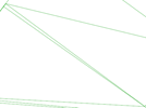
The picture below explains the situation. It shows the same data as above, but with the addition of the road surface triangles (in grey) and the flow arrows (in cyan):
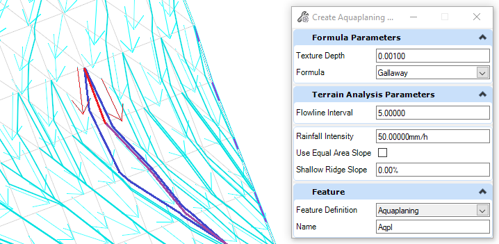
Two flow arrows have been drawn in red. These both point away from their common triangle side, which means that the triangle side is a ridge, which is shown in a thicker red line. Because it's a ridge, two flow lines (shown in dark blue) are created - both starting at the start of the ridge. A third flow line (shown in purple) is also created, starting at the end of the ridge. If the ridge was longer than the value used for the Flowline Interval property, then further pairs of flow lines would be created, flowing away from the ridge on either side.
The Shallow Ridge Slope property can be used to improve the flow lines, as shown below:
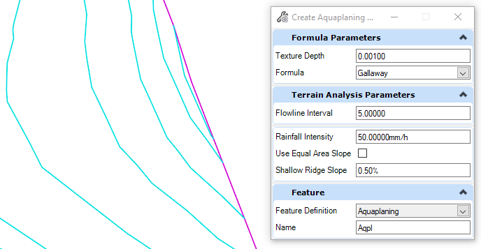
It shows the same data again, but using a value of 0.5% for the Shallow Ridge Slope. The difference in slope between the two flow arrows highlighted in red is less than 0.5%, so the ridge is regarded as being shallow, and is ignored.
Care should be taken not to use a value that is too high, as this could potentially remove ridges that are a valid result of the road surface geometry.
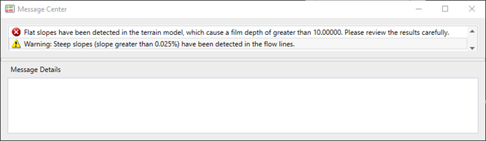
Flat Slopes
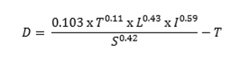
D = Water film depth above the top of pavement texture (mm).
T = Average pavement text depth (mm) (See Texture Depth section.)
L = Length of drainage path (m) (See Drainage Path section.)
I = Rainfall intensity (mm/h) (See Rainfall Intensity section.)
S = Slope of drainage path (%) (See Drainage Path section.)
Steep Slopes
Steep slopes can occur when a flow line intercepts the edges of a very narrow triangle or triangles left outside of (or extending beyond) the road surface. A warning message is shown inside the Civil Message Center if one or more slopes are greater than Maximum Slope set in the dialog.


Steep slopes detected at the start of the flow line are ignored.
The message is shown in the Civil Message Center.