Line of Sight
This tool is used to generate line sight for the roadways. It uses a feature definition that allows you to specify the symbology that represents the sight distance achieved.
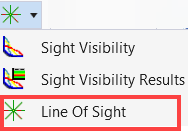
You can access this tool from the following:
Ribbon: Terrain > Analysis > Line of Sight
There are two methods available in the Line-of-Sight tool as explained below.
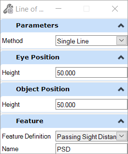
Single Line Method
You can pick a corridor, design or existing surface then select the height for the eye position from the existing surface. Then select the input object position. Accept the selection and a single line of sight is displayed. Where the green color line represents the visible sight, and the red color is a line of sight not visible from the object.
Radial Method
The radial method gives a 360-degree view of an object from a selected position.
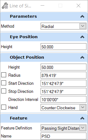
The table below explains the parameter of the Radial method.
| Settings | Description |
|---|---|
| Parameter | |
| Method | Allows you to select either Single Line or Radial method. |
| Eye Position | |
| Height | Allows you to set the height of the driver's eye above the road surface or terrain model. |
| Object Position | |
| Height | Allows you to set the height of the object or hazard above the road surface or terrain model. |
| Radius | Allows you to define the radius of the Line of Sight. |
| Start Direction | Allows you to set the start direction of the Line of Sight. |
| Stop Direction | Allows you to set the stop direction of the Line of Sight. |
| Direction Interval | Allows you to set an interval to the selected directions of the Line of Sight. |
| Hand | Allows you to set either a clockwise or counterclockwise direction. |
| Feature | |
| Feature Definition | Allows you to select the feature definition. |