Design File Settings
Used to change design file-specific settings.
You can access this dialog from the following:
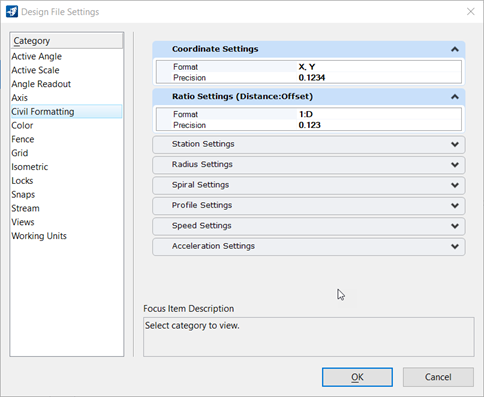
The Civil Formatting category provides options for civil settings that control civil annotation within the design file. See the MicroStation help for details on all other categories.
Coordinate Settings

Controls the display and precision of their coordinates within any of the civil dialogs. In addition, this setting also controls how any inputted coordinates are interpreted. For example, if set to "X, Y" then all coordinates are interpreted and displayed as being in the "X, Y" format. If set to "Nothing, Easting" then the same applies.
Ratio Settings - (Distance:Offset)

Controls the display and precision of ratios within any of the civil dialogs. In addition, this setting also controls how any inputted ratios are interpreted. For example, if set to "1:D" then all ratios are interpreted and displayed in this format (1:100, 1:50, etcetera). If set to "D:1" then the ratios are similarly displayed and interpreted (5:1, 10:1, etcetera).
Station Settings

Controls the format, delimiter and precision of the station values to be used and displayed in the civil dialogs. In addition, there are two options to control how equations are represented within the station values.
- By Name - Station equations represented by user-defined character preceding the station. (A100+00, B105+00, etcetera).
- By Index - Station equations represented by hard-coded numeric values appended to the stationing. Numbers start at 1 and are in ascending order. (100+00 R 1, 105+00 R 2, etcetera).
Radius Settings
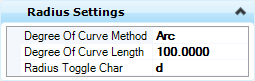
- Degrees of Curve Method - Two options are available, Arc and Chord.
- Degree of Curve Length - This sets the standard definition of a 1^ curve.
- Radius Toggle Char - This allows the user to specify which character will be used within the civil dialogs to 'toggle' between a radius definition and a degree of curve definition.
As described in the Preferences topic, when Bentley Civil is loaded, there is a Civil Formatting panel of settings. One of these settings is the degree of curve toggle.

Radius Toggle is the keystroke used to define degree of curve instead of radius in. Radius Toggle can be used in any command where an arc is defined. By default, the commands prompt for radius as shown below.

The radius can be changed to a degree of curve by using the toggle as shown below. Key-in d followed by the degree of curve value.

The degree of curve is seen at the prompt.
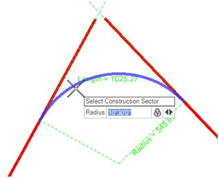
Degree of curve is persisted in the rule as shown in the manipulators.

Degree of curve is persisted only if locked.
Key-in d again if you need to switch back to radius in the same command instance.
The next time you start the arc command, it will default back to radius mode.
If you use the pass-thru point to dynamically manipulate the arc, it will switch back to radius persistence.
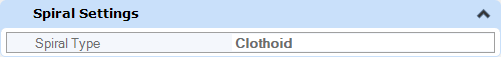
Spiral Settings
Profile Settings
Controls the precision and display or input formats of slopes and ratios within a profile context. In addition, sets the default Vertical Curve Parameter Format (Radius, K Value or M Value).

Use the Profile settings to control the precision and display/input formats of slopes and ratios within a profile context. Click the Vertical Curve Parameter field to set K Value:
-
K Value Length of Curve/Change in gradient. Example, K = L/A)
-
Radius R-Value equal to 100*K. Example, R=100*L/A); Produces a parabola (called radius because it produces a parabola that approximates a circular curve of radius = 100*K)
-
EqvRvalue equal to 100*Kvalue
Speed Settings
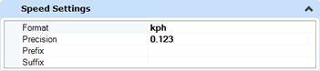
Controls the units of speed and the display of decimal places.
Acceleration Settings
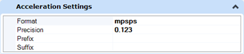
Controls the units of acceleration and the display of decimal places.