Analyze Point
 Used to dynamically review
information about a selected 2D or 3D design element, terrain model or mesh.
Used to dynamically review
information about a selected 2D or 3D design element, terrain model or mesh.
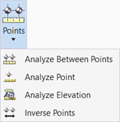
You can access this tool from the following:
Use the Analyze Point tool to dynamically review information about a selected 2D or 3D design element, terrain model or mesh.
The results are based on the type of element selected. For example if a 2D MicroStation element is selected, the results include Station, Offset, X, Y, and Direction.
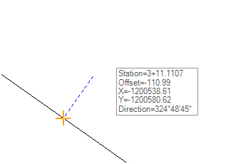
In this case, the stationing is based on 0+00 at the origin of the element, while the Offset is based on the distance from the cursor perpendicular to the element. If a 3D element is selected, elevation and slope is now displayed.
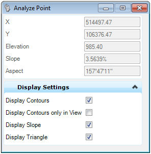
When terrain models or meshes are utilized, information about the triangle wherein the point lies is also displayed. This may include slopes and aspects. Contours may also be drawn.
Prerequisites
A 2D or 3D MicroStation element, civil geometry element, terrain model or MicroStation mesh is needed
Workflow for Non-Surface Elements
-
Start the tool.
-
Select the 2D or 3D element.
-
As the cursor moves point information is reported in the dialog and in tool tip.
Workflow for Terrain Models or Meshes
-
Start the tool.
-
Select the terrain model or mesh.
-
As the cursor moves point information is reported in the dialog and in tool tip. If the cursor point is outside the terrain model or within a void, only a message is displayed, i.e.,no point data.
-
Use the ALT keyboard button to change dialog options to display contour, triangle, elevation, slope arrow.
-
A data point draws the displayed contours on the default level.
Options
|
Settings |
Description |
|
Display Contours |
Display all contours of the same elevation of the user-selected point. For example, if the elevation of the point is 153.64, then all contours in the terrain model with the elevation of 153.64 are displayed. |
|
Display Contours only in View |
Rather than displaying all the contours of the user-selected point, only the contours within the view are displayed. This is useful for very large terrain models |
|
Display Slope |
Displays the slope of the triangle (compared to a horizontal plane) in terms of percent |
|
Display Triangle |
Highlights the triangle wherein the user-select point is located. |

|
Settings |
Description |
|
Station |
Reports the station location of the cursor location based on the user-selected horizontal geometry element. |
|
Offset |
Reports the offset of the cursor location based on the user-selected horizontal geometry element. |
|
X |
Reports the X coordinate along the reference element. |
|
Y |
Reports the Y coordinate along the reference element. |
|
Elevation |
Reports the elevation (in master units) of the user-selected point. |
|
Slope |
Reports the slope (in terms of percent) of the triangle wherein the user-selected point is located. The slope is measured from a horizontal plane. |
|
Aspect |
Reports the aspect of the triangle wherein the user-selected point is located. The aspect describes the direction that the triangle plane faces. Aspect ranges are expressed in degrees. The north axis is defined as zero degrees and angles increase in a clockwise direction. Therefore, zero degrees points north, 90 degrees points east, 180 degrees points south and 270 degrees points west. A level triangle is assigned a default aspect of 360 degrees. |