Geometry Builder
 The Geometry Builder tool is
another way to define and edit geometry, especially for ROW and Parcel
definition. Here we can create geometry as much as we want in a file and save
it for later and can be recall them for further editing and again allows to
save them back.
The Geometry Builder tool is
another way to define and edit geometry, especially for ROW and Parcel
definition. Here we can create geometry as much as we want in a file and save
it for later and can be recall them for further editing and again allows to
save them back.
- Allows quick input of plan data, for example, centerlines.
- Allows editing existing, creating new geometry and MicroStation graphics.
- Allows quick input of deed/legal descriptions ie: Surveyor-friendly tabular Input.
- Allows you to automatically apply rules.
- Allows you closing calls.
- Allows to archive Geometry to XML Files.
- Allows you to Report Generation
You can access this tool from the following:
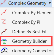
Ribbon: Geometry > Horizontal > Complex Geometry split button.
Geometry Builder Tool dialog
The left side of the interface displays alignments. Multiple alignments are supported as well as locks. The right side of the interface is the main interface area for entering the legs of the geometry. The geometry information area at the bottom of the interface displays the perimeter area and closure information. It also displays a notification message once a civil element is placed in the active file.
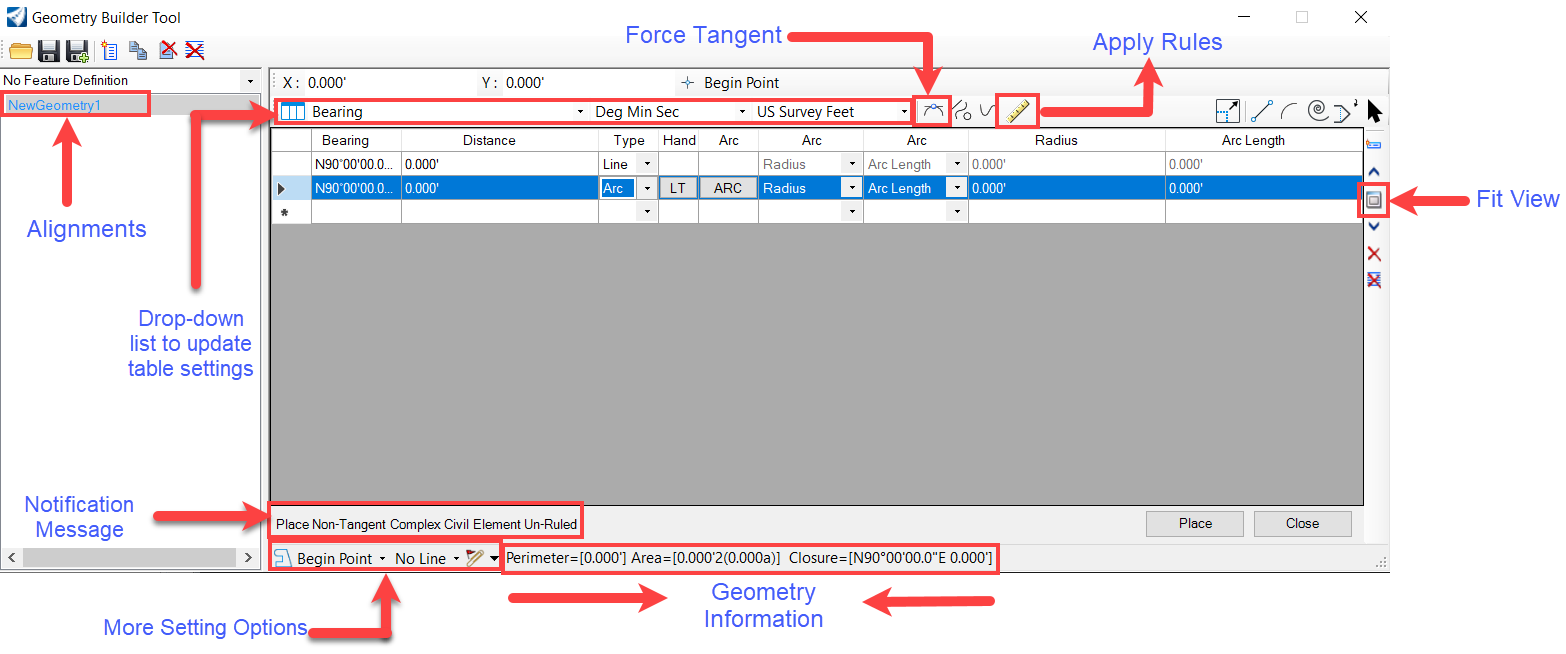
The table shown below describes the Geometry Builder tool options.
| Settings | Description |
|---|---|
| General Tools | |
| Open File | Allows you to open an existing file. |
| Save File | Allows you to save the currently open file |
| Save File As | Allows you to open the save dialog to save the item with a new name. |
| Add New Geometry | Allows you to add a new geometry name and feature definition. |
| Copy Selected |
Allows you to copy selected items. |
| Deleted Selected |
Allows you to remove selected items. |
| Delete All Items | Allows you to select all items for deletion. |
| Lock Tools | |
| Tangent Restriction | Allows you to toggle between the placement and enforcing elements being tangent. |
| Simple/Complex Elements | Allows you to toggle between creating simple or complex elements. |
| Create Graphics Elements | Allows you to toggle between creating civil elements and graphic elements. |
| Ruled-Unruled Geometry | Allows you to toggle between creating ruled and un-ruled civil elements. |
| Modify Tools | |
| Modify Item | Allows you to move the item to a new location. |
| Insert Line |
Allows you to place or construct a line |
| Insert Arc |
Allows you to place or construct a circular arc. |
| Insert Spiral |
Allows you to place a transitional spiral as a B-spline curve. |
| Insert Vertex |
Allows you to insert a vertex in an element |
| Insert Element |
Allows you to place select or deselect elements for modification or manipulation. |
| Other Tools | |
|
Insert New Item |
Allows you to insert the new item. |
|
Move Up |
Allows you to move items up. |
|
Fit View |
Allows you to adjust the view magnification so that the entire model is visible in the view. |
|
Move Down |
Allows you to move items down. |
|
Delete |
Allows you to delete selected items. |
|
Delete All |
Allows you to delete all items at once. |
| Units Supported |
Allows you to p lace Bearing, quadrant, azimuth, and direction. Degrees, degree minute, degree minute second, gradian, radians. and Linear units. |
| Place Button | Allows you to write the geometry to the DGN. |
| Report Button | Allows you to generate a filtered report of selected elements. |


