Elevation Difference Grid
 Elevation Difference Grid
tool supports a variety of grid generation and cut/fill element templates.
Elevation Difference Grid
tool supports a variety of grid generation and cut/fill element templates.
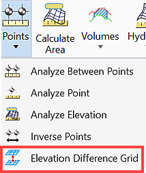
You can access this tool from the following:
Elevation Difference Grid dialog is explained below.
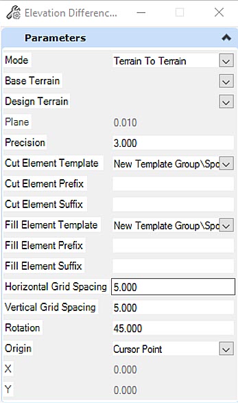
Mode: It defines two selections Terrain to Terrain and Terrain to Plane.
Base Terrain: It will prompt to pick graphically once you click the pull-down arrow.
Design Terrain: It will prompt to pick graphically once you click the pull-down arrow.
Precision: It is the precision of the cut or fill value
Cut Element Template: It defines the element template for the cut text. The element template defines the text style and cell to be placed at the grid point. Active symbology will be used if none defined.
- Prefix: It is a prefix string that is to be appended in the beginning of the Cut value.
- Suffix: It is a suffix string that is to be appended in the end of the Cut value.
Fill Element Template: It defines the element template for the fill text. The element template defines the text style and cell to be placed at the grid point. Active symbology will be used if none defined.
- Prefix: It is a prefix string that is to be appended in the beginning of the Fill value.
- Suffix: It is a suffix string that is to be appended in the end of the Fill value.
Plane: It defines the elevation of a horizontal plane
Horizontal Grid Spacing: It defines the horizontal grid spacing value distance between columns.
Vertical Grid Spacing: It defines the vertical grid spacing value distance between rows.
Rotation: It defines an angle of rotation and should be applied clockwise.
Operation: The grid will only be placed in the area where the two terrains overlap even if the data point is given off the terrain. The data point is defined as one point in the grid.
If a fence is present the grid will only be placed inside the fence and where the two terrains overlap.
If using a plane, the whole terrain should be gridded unless a fence is present. If a fence is present, it will only grid the area inside the fence.
Annotation and Element Templates
Element Templates are used to draw the cut text and fill text. The annotation for the grid points will be created using the text style defined in the element template.
Annotation will be created at run time.
- String: <Cut Prefix><Cut Value(Precision)><Cut Suffix> Example: C: -1.2'
- String: <Fill Prefix><Fill Value(Precision)><Fill Suffix> Example: F: 1.2'
The value will be represented by one of the following:
- Cut Value: (Elevation of Design Terrain) - (Elevation of Base Terrain) <= 0 OR (Elevation of Design Terrain) - (Elevation of Plane) <= 0
- Fill Value: (Elevation of Design Terrain) - (Elevation of Base Terrain) > 0 OR (Elevation of Design Terrain) - (Elevation of Plane) > 0
Cursor Point: It will help user to define a data point at the lower left start point of the grid to be placed. (X and Y fields will be dithered for this method)
Fixed Point: It will provide the X and Y values in the X and Y fields for the grid point.