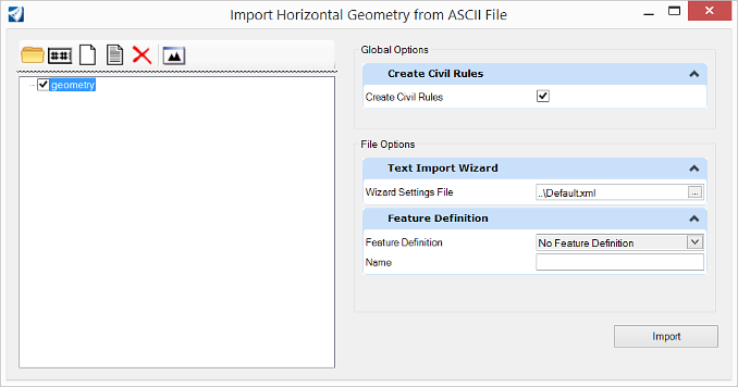
Import Horizontal Geometry from ASCII File
 Imports horizontal geometry
element from an ASCII file via a text wizard.
Imports horizontal geometry
element from an ASCII file via a text wizard.
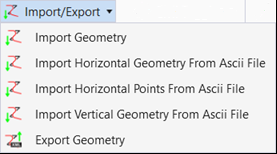
You can access this tool from the following:
Importing Various Data Types
This topic provides details on the import process for the various data types that can be imported using the Text Import Wizard.
Cogo Points
Each line is processed as one cogo point. If the filter does not specify the point name, a name is generated in the same manner as the Add Cogo Point command. If station-offset data is provided instead of easting-northing-elevation data, an active horizontal alignment must be present. If a point's station-offset data does not fall within the horizontal station range, the point will not be imported. Each cogo point is then added to the active cogo buffer and after all points have been added, the InRoads Explorer is updated.
Data Example - Point Name, Northing, Easting, Elevation
Cogo1 417289.44 194301.93 0.00
Cogo2 417233.32 194384.69 0.00
Cogo3 417179.75 194468.90 0.00
Cogo4 417186.60 194566.65 0.00
Cogo5 417211.60 194663.48 0.00
Cogo6 417236.60 194760.30 0.00
Cogo7 417255.53 194857.96 0.00
Horizontal Alignments
Each line is processed as a horizontal PI except the last line, which is processed as the last point of the alignment. As each PI is processed, it is added to an array. After all data has been loaded, each PI and related circular arcs and transition spirals is inserted into the newly created alignment whose name, description, and style were specified by the user through the Geometry Options dialog. After all PIs have been added, the alignment is inserted into the active Geometry Project in the InRoads explorer and made active.
Data Example - Northing, Easting, Radius, First Spiral Length, Second Spiral Length
1000 1000
2000 2000 500 100 100
3000 1000 500
4000 2000 500 75 125
5000 1000
The preceding example is the same as adding PIs with the Geometry>Horizontal Curve Set>Add PI at the following coordinates:
1000, 1000
2000, 2000
3000, 1000
4000, 5000 and
5000, 1000.
Then using Geometry>Horizontal Curve Set>Define Curve to add the following curve sets:
- An SCS type of curve set with a radius of 500, a leading clothoid spiral of length 100, and a trailing clothoid spiral of length 100
- An SCS type of curve set with a radius of 500 without spirals
- An SCS curve set with a radius of 500, a leading clothoid spiral of length 75, and a trailing clothoid spiral of length 100
Geometry Options (Text Import Wizard)
The Geometry Options dialog appears when you import a horizontal or vertical alignment. The file name is displayed in the dialog title.
Horizontal Alignment Wizard
Reads a file when data is defined by:
The software determines all geometry from the point types and coordinates. A transitional spiral's type is defined by File > Project Options > Geometry and Spiral Definition. The transition spiral's length is the station difference between the TS and SC.
Use these keywords of the Horizontal Alignment wizard:
Define multiple filters to read these types of files.
Point Order
The following assumptions:
- The points are from the start of the alignment to the end of the alignment
- The points for a circular arc must be start of the circular arc (i.e. PC), center of circle (i.e. CC) and followed by the end of the circular arc (i.e. PT)
- The points for a transition spiral must be start of the spiral (i.e. TS), spiral's point of intersection (i.e. SPI) and followed by the end of the spiral (i.e. SC)
The order is important so that the software can determine whether a series of points is a line, circular arc or a transition spiral. Whether an element is a circular arc or a spiral, is based upon the position of an off alignment point and the previous point and next point. If the distance from the previous point to the off alignment points and the distance from the off alignment point to the next point is equal then the element is a circular arc. Otherwise the element is a transition spiral. In the later case the software must be able to compute the starting radius and the ending radius of the spiral. This is accomplished by examining points prior to the spiral and after the spiral.