Import Geometry
 Imports geometry elements that
are stored in the cogo databases if they are MX (FIL), InRoads (ALG or FIL), or
GEOPAK (GPK) elements.
Imports geometry elements that
are stored in the cogo databases if they are MX (FIL), InRoads (ALG or FIL), or
GEOPAK (GPK) elements.
You can access this tool from the following:
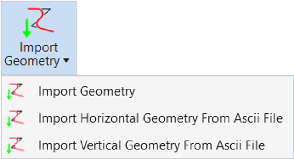
- Ribbon: Geometry > General Tools > Import/Export split button
- Ribbon: Home > Model Import/Export > Terrain Import split button
Civil Geometry tools can import geometry elements that are stored in the cogo databases if they are MX (FIL), InRoads (ALG or FIL), or GEOPAK (GPK ) elements.
Workflow
-
Click Import Geometry. The Import Geometry dialog displays. All three file types are available.
-
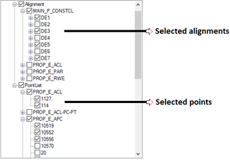
Select the geometry database. When selected, the geometry database is queried and a checklist displays.
-
Check the elements to be imported and click the Import button.
Geometry Import dialog Additional Options
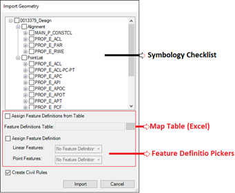
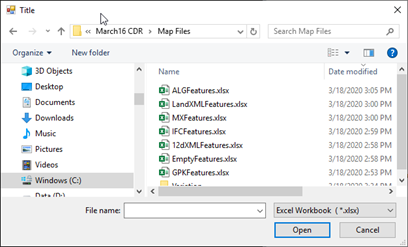
- Assign Feature Definition from Table: Specifies an Excel workbook and uses a mapping table to assign Feature Definition to matching Style/Feature symbology name (feature name if GENIO or MX file) in the checklist.
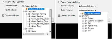
- Assign Feature Definition: Allows selecting Feature Definition. One for non-points (Alignment/Lines/Curves/Spirals) and one for point list. The two Feature Definition (non-points and points) are assigned to all elements chosen in the checklist.
The two options can be selected at the same time to combine the solutions or independently selected one by one.
Selecting only Assign Feature Definition from Table
To each selected style/feature symbology name (Map From) the corresponding Feature Definition (Map To) is assigned to the elements selected in the check list.
Important: If there is no matching, "No Feature Definition" is used.
Selecting only Assign Feature Definition
All selected elements are assigned to the feature definitions chosen in the combo boxes.
Selecting Both options
First, the software looks for a match in the table.
If no match is found, the Feature Definition chosen in the combo box is used.
No selections
"No Feature Definition" is assigned to all elements selected.
Table Definitions
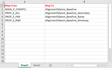
The table used here is an Excel spreadsheet that maps the Style/Symbology values coming from the imported file to existing feature definitions.
The search for a match starts at the top to the bottom and the first match found is used.
Th spreadsheet has the following characteristics:
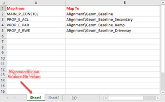
- The first worksheet is used for Alignment/Linear feature definition mapping.
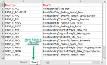
- The second worksheet is existing and is used for Point Feature Definition mapping.
- Other worksheets are ignored.
- Any name can be assigned to the worksheets.
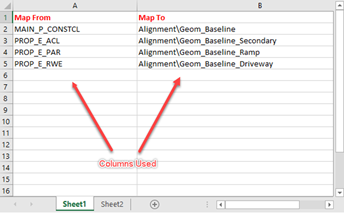
- Only the first two columns of the worksheet are used. Other columns are ignored.
- The first row is ignored as well. It can be used as header and can contain any value.
- The first column contains the values (Style/Simbology) coming from the imported file.
- The second column has the feature definition that is assigned to the elements with the corresponding Style/Simbology (or feature name).
- Rows the with first or second cell empty are ignored.
Wildcard
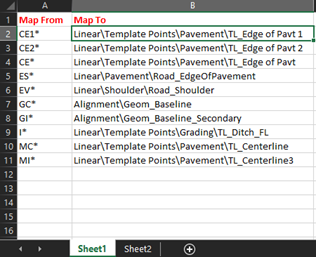
The wildcard * can be used in the first column as shown in the image. It can have only one wildcard per cell at the beginning or at the end of the value.