Modify Bridge
The bridge can be modified in multiple ways.
Modify the Bridge Horizontal/Vertical Alignment
The bridge itself does not have a different alignment than the road, therefore modifying the road alignment will modify the bridge alignment.
Note: When modifying the bridge alignment for pre-stressed girder bridge you might see the girders appearing outside the bridge vertically or horizontally. The software does not re-compute the number of spans, so you could manually increase the number of spans to avoid that behavior.
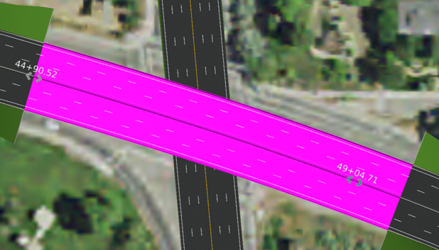
Modify the Bridge Span Length
It is possible to modify the bridge length using the manipulator handler in the main scene, by moving those interactively. It is also possible to modify the Start and End Stations using the text manipulators.
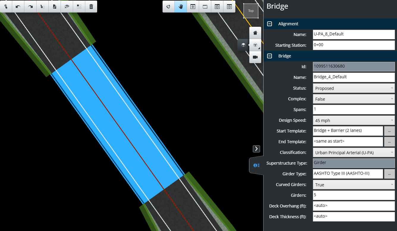
Bridge Properties
Like other objects, the bridge holds properties that can be modified. Some are non-geometric and others are geometric (changing the bridge geometry). Accessing the bridge properties can be done by clicking on the bridge itself, which will activate the right drawer area.
|
Property |
Description |
|
Alignment Name |
Assigned property by default at creation time. However, the user can change this property anytime to help identify objects. Changing this property will not change the bridge geometry. |
|
Status |
Determines the life cycle of an object. It can be either Proposed, Existing or Construction. The Proposed status will determine if the object is used in the cost and quantities calculation. Changing this property will not change the bridge geometry. |
|
Complex |
Determines whether the bridge is classified as complex or non-complex. Complex bridges have longer spans between piers and are steel instead of concrete. They also have a higher cost rate per square foot. |
|
Spans |
Determines the number of spans, the number of support is the number of span minus one. Changing this property will change the bridge geometry to the new input value. |
|
Design speed |
This is the road speed on which the bridge has been created and it is used for internal calculations. Changing this property will not change the bridge geometry. |
|
Start Template |
Modifies the bridge deck template at the start of the bridge. Changing this property will change one end of the bridge geometry to the new input value. |
|
End Template |
Modifies the bridge deck template at the end of the bridge. Changing this property will change one end of the bridge geometry to the new input value. |
|
Classification |
Is the AASHTO road classification. This property comes from the road itself. Changing this property will not change the bridge geometry. |
|
Girder type |
Changes the girder type of the bridge. Changing this property will change the bridge geometry to the new input value. |
|
Number of girders |
Changes the number of girders. Changing this property will change the bridge geometry to the new input value. |
|
Deck Bottom Width |
The Deck Bottom Width field only applies to box bridges. |
|
Deck Overhang |
The Deck Overhang field applies to box and girder bridge types. The input value is the amount of overhang to one side of the bridge. The overhang will be applied to both sides. Default values are automatically input according to the previous calculations. The user may enter values to override the default. To return to the default behavior, delete the input value. |
Bridge Deck Thickness
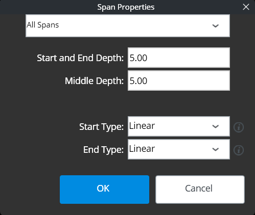
It is possible to edit the bridge deck thickness and create arch bridges by clicking the [...] icon next to the Spans field in Bridge Properties. Doing so will open the Span Properties dialog.
|
Property |
Description |
|
Start and End Depth |
Defines the Start and End Depth of the bridge deck. |
|
Middle Depth |
Defines the Middle Depth for the bridge deck. |
|
Start Type |
Choose a type from the drop-down list. Explanations for the types can be viewed by clicking the information icon next to the field. |
|
End Type |
Choose a type from the drop-down list. Explanations for the types can be viewed by clicking the information icon next to the field. |
Modify the Bridge Type
It is not possible to change the bridge type. However, it is possible to delete and recreate the bridge and change the bridge type when re-creating it.
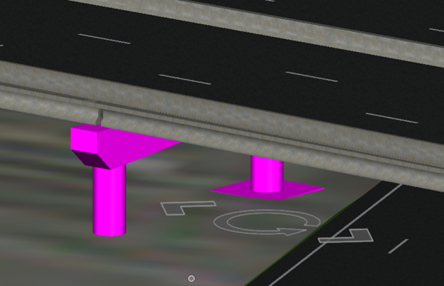
Edit Supports
The bridge supports can be edited individually or in bulk from the main Bridge Properties.
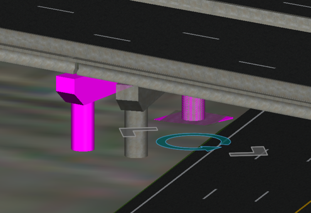
Moving and Rotating / Skewing Bridge Support
It is possible to move or rotate the bridge support by using the handler manipulator of the support. To activate those manipulators, select the object: the rotation and move manipulators will appear.
To move the support, click on the straight arrows and move the mouse in the desired direction. It is not necessary to hold the mouse key to move it. To accept the new location, left click again.
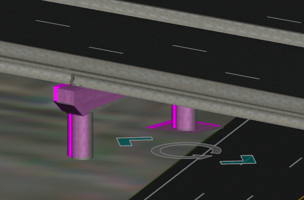
To rotate the support, click on the rotating arrow and move the mouse around the rotation axis. Left click to accept the new rotating angle.
Delete Support
It is possible to delete a support by selecting it and press on the Element Deletion Tool or the Delete keystroke.
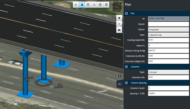
Support Properties
As most other objects the support holds properties than can be modified, some are non-geometric or others are geometric (have an effect on the support geometry). Access the support properties by clicking on the support itself, which activates the right drawer area.
|
Property |
Description |
|
Name |
Assigned property by default at creation time. However, the user can change this property anytime to help identify objects. Changing this property will not change the bridge geometry. |
|
Status |
Determines the life cycle of an object. It can be either Proposed, Existing or Construction. The Proposed status will determine if the object is used in the cost and quantities calculation. Changing this property will not change the bridge geometry. |
|
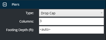
Type |
Changes the support type. |
|
Footing Depth (ft.) |
Positive values move the footing down to provide more 'cover' over the top of the concrete footer. Negative values move the footing up. |
|
Skew (angle) |
Changes the rotation angle at a fixed angle, more precise than the graphical rotation tool. Specify a value between -80 degrees and 80 degrees. |
|
Distance along bridge |
Changes the station along the bridge for the support. This method is more precise than the graphical move tool. |
| Extension (Left) |
|
| Extension (Right) |
|
|
Column Type |
Changes the number of columns. Note that this does not apply to certain types of support (support having only one column by nature). |
|
Column diameter |
Changes the diameter of the columns. |
|
Column Spacing Column Count |
Changes the number of columns. |
|
Column Spacing Spacing 1-2 |
Defines spacing between columns. |
Edit Abutments
The abutment can be modified after placement.
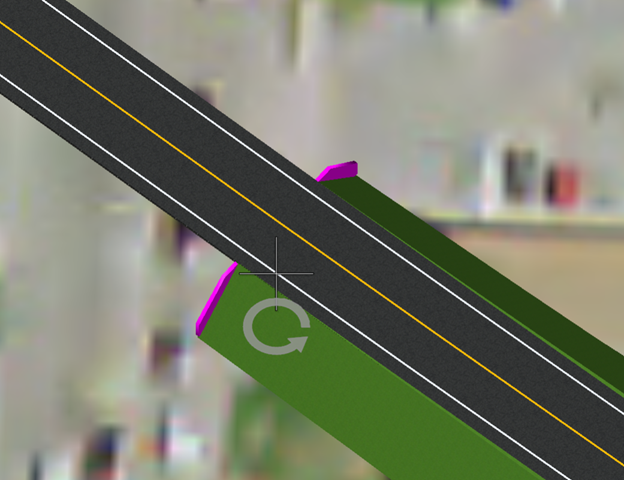
Skewing Abutment
It is possible to rotate the bridge abutment by using the handler manipulator on the abutment. To activate this manipulator, select the object and the rotation manipulator will appear. To rotate the abutment, click on the rotating arrow and move the mouse around the rotation axis. Left click to accept the new rotating angle.
Abutment Properties
As most other objects, the abutment holds properties than can be modified. Some are non-geometric or others are geometric (have an effect on the abutment geometry). Accessing the abutment properties can be done by clicking on the support itself, which will active the right drawer area.

|
Property |
Description |
|
Name |
Assigned property by default at creation time. However, the user can change this property anytime to help identify objects. Changing this property will not change the bridge geometry. |
|
Status |
Determines the life cycle of an object. It can be either Proposed, Existing or Construction. The Proposed status will determine if the object is used in the cost and quantities calculation. Changing this property will not change the bridge geometry. |
|
Skew angle |
Changes the rotation angle at a fixed angle, more precise than the graphical rotation tool. Specify a value between -80 degrees and 80 degrees. |
|
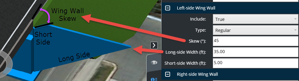
Include Right/Left Wing Wall (False / True) |
Controls the existence of the wing wall on each side of the abutment. |
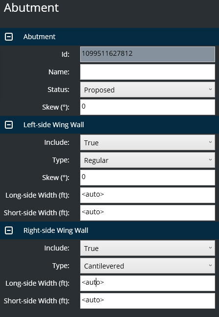
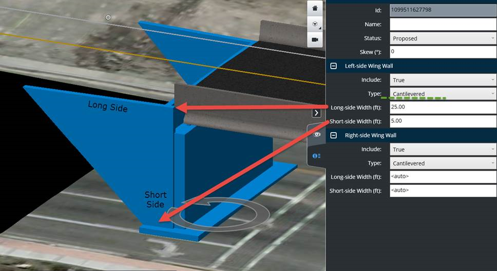
| Type | Regular or Cantilevered. |
| Skew (angle) | Angle in degree. Available for the Regular wing wall type only. |
| Long-side Width | By default, the <auto> value will attempt to size the lenghts of the top and bottom of the wing wall to fit the template slopes at the bridge approach. The size can be edited by typing a new value. |
| Short-side Width | By default, the <auto> value will attempt to size the lenghts of the wing walls to fit the template slopes at the bridge approach. The size can be edited by typing a new value. |
Below are examples of both Regular and Cantilevered.