Place Signal

Furniture can be placed relative to a linear asset in two different ways, as follows:

In the above example, a piece of furniture (the red dot) is placed at a distance along a linear asset. In Signal Sighting, this can either be measured by a meterage from the start of the linear asset, or as a meterage from a datum point.
The datum point can be an XYZ location, or the defined point of any other piece of furniture. In particular, mileposts can be used to place signals relative to, and signals can be used to place AWS magnets relative to.
All meterages are measured against the same linear asset. This would normally be the track centerline.
Once the final track location has been identified, a horizontal and vertical offset are applied. This can either be relative to the track centerline, or relative to the near rail (in which case cant is also taken onto account)
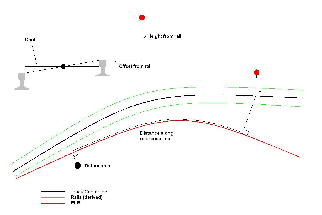
In the above example, a datum line has been introduced as well. These are often used to ensure that linear measurements along multiple tracks are consistent.
In this case, the datum is located against the reference line (e.g. Engineers Line Reference alignment), and the distance along the reference line is calculated. A normal is then dropped from the reference line to the track.
Once the final track location has been identified, a horizontal and vertical offset are applied. This can either be relative to the track centerline, or relative to the near rail (in which case cant is also taken onto account).
To place new furniture, select "New". This brings up the following dialog:

The user then selects the dgn representing the signal to place (it must previously have been designed using the "Edit Furniture Models" tool.
Alternatively, to edit an existing signal location, click "Select". This then brings up the following dialog:
The dialog shows all of the items currently in the drawing, and allows the user to select an item from the list,
 alternatively click the Pick
Furniture Instance button and select the furniture graphic item in one of the
Microstation views.
alternatively click the Pick
Furniture Instance button and select the furniture graphic item in one of the
Microstation views.
Once the signal to place has been defined, the user can proceed to place it.
This dialog contains tools for selecting features and locations in the Microstation view.
 Pick Feature - Pick the BRT
feature in the Microstation view
Pick Feature - Pick the BRT
feature in the Microstation view
 Pick Point - Pick the 3d location
for an insertion point in the Microstation view
Pick Point - Pick the 3d location
for an insertion point in the Microstation view
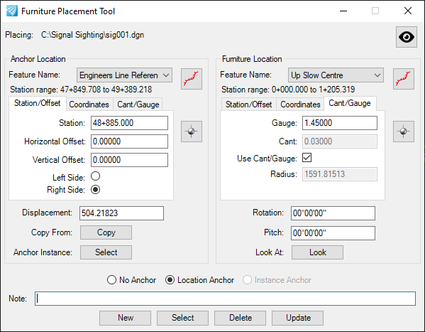
To place a piece of furniture at an offset along a linear feature use only the right hand side of the form.
The feature name (for the linear asset to measure along) is in the drop-down at the top of the form. Once selected, the linear range for the feature is displayed (for information only - in this case 0 to 1531.649 meters).
A value can then be typed into the "Station" textbox, for the distance along the linear feature (from its start) to place the furniture. The horizontal and vertical offsets can also be defined.
The default angle is 0: this is measured relative to the track, and is not an absolute rotation. An angle can be entered in degrees to rotate the furniture relative to the track. Alternatively, the furniture can be rotated to point at another nominated point on the track - this is often used for signals. Selecting the "Look" option brings up the following dialog:

In this dialog the user defines the location at which the furniture is to point. It is used in the same way as the define furniture location tab (described elsewhere). Defining a linear point and then pressing "OK" will point the furniture at the defined point.
If furniture is to be located at an offset from a datum point, then the "Use Anchor Point" option should be selected (bottom left in the following screenshot).

The left hand side of the dialog is now used to define the datum point, and the right hand side is used to define the location of the furniture. The "Displacement" textbox is used to define the distance along the linear feature from the datum to the furniture.
If the feature names for the left and right side of the dialog are the same, then only a single linear feature is used - this is the first case listed at the top of this section.
If two different feature names are used, then the feature name on the left is the name of the reference line, and the feature name on the right is the name of the track line.
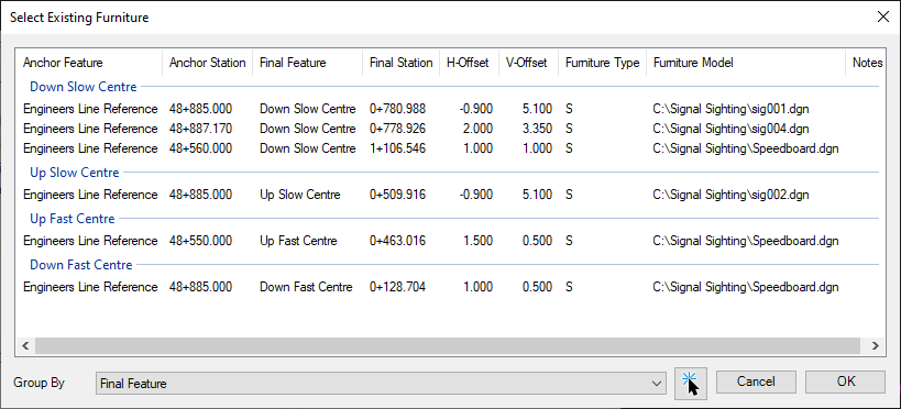
To select the location of an existing piece of furniture (e.g. a signal or a milepost) to use as the datum point, select the "Copy" button. This opens the following dialog:

The list of items in this dialog can be grouped by furniture type, anchor feature, final feature or furniture model to enable easy selection of items in a large list. Items can also be sorted into numerical or alphabetical order by clicking the column title.
From this dialog select the piece of furniture to use as the datum, and press "OK". The coordinates of the furniture selected will be placed into the dialog.
The point selection dialogs all contain the same control, with three tabs.
Tab 1

This tab is used to select a location along a linear feature by station (distance from start). The horizontal and vertical offset from this point can also be selected, as well as which side of the linear feature is used.
Tab 2

This tab shows the location as X, Y and Z coordinates. These can be edited by the user if required, and will update the values in the other tabs if possible and appropriate.
Tab 3
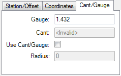
This tab is used to determine is Gauge and Cant need to be applied or are available in the source data. Gauge is measured in meters, and will default to 1.432m. Cant is read from the alignment used for the track, if it is available.
After an item has been placed the track radius is displayed in this tab.