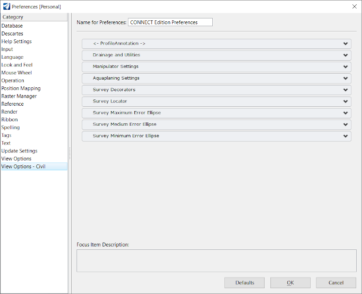
Preferences
Used to set user preferences - settings that control how the product operates.
Preferences are not design file-dependent and cannot be saved in the design file. However, they are saved in the user preferences file pointed to by the MS_USERPREF configuration variable when you click the OK button.
You can access this dialog from the following:
View Options - Civil is the one category of the Preferences used by OpenRoads Designer. (For help on the rest of the categories, see the MicroStation help.)
View Options - Civil category provides settings for the cursor prompt, manipulators, and various operational toggles.
Cursor Prompt Dialog
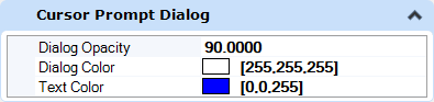
Specifies the preferences for Cursor Prompt window that follows the mouse. The cursor prompt shows the message displayed in the lower left field of the Status Bar. It guides you step by step as you perform an operation with a tool.
Drainage and Utilities

|
Option |
Description |
|
Orient Top to Surface Max Slope |
The Utility category of the properties of a node includes "Use Slope of Surface." If this is enabled, then "Orient Top to Surface Max Slope" sets the maximum value of the slope. Values above this will be ignored in the 3D model, and the slope of the top of the node will be flat. |
|
Profile Node Drawing |
The default setting for how a node will be represented when creating a profile run. This default can be overridden in the dialogs for creating profile runs, and in the properties of a profile run. |
|
Show Hydraulic Grade Line |
This preference controls whether the Hydraulic Grade Line is shown in the Civil profile model of a profile run, for storm or sanitary conduits. |
|
Show Energy Grade Line |
This preference controls whether the Energy Grade Line is shown in the Civil profile model of a profile run, for storm or sanitary conduits. |
|
Hydraulic Grade Line Color |
The color of the Hydraulic Grade Line in the Civil profile model of a profile run, for storm or sanitary conduits. |
|
Energy Grade Line Color |
The color of the Energy Grade Line in the Civil profile model of a profile run, for storm or sanitary conduits. |
|
Show Conduit Wall Thickness in Profile |
This preference controls whether the wall thickness of conduits is shown in a profile run, in the Civil profile model. |
|
Hide 3D Model on Creation |
This preference controls whether the display of the 3D model is turned off when a Drainage and Utilities project is created in a design file. |
|
Show Connected Conduits in Profile |
If this option is enabled, the nodes in a profile run will include graphics to show connected conduits. Connected conduits are conduits which are not included in the profile run, but are connected to nodes that are included. For example, a node might have three incoming conduits and an outgoing conduit. One of the incoming conduits, and the outgoing conduit, usually is included in the profile run, which leaves the other two incoming conduits. If this option is enabled, these two conduits are shown, in the appropriate shape (circle, box, etc). This shape honors the vertical exaggeration, and includes the wall thickness, if this property is available for the conduit shape, and the Show Conduit Wall Thickness in Profile property is set to true. If Show Connected Conduits in Profile is set to False when a profile run is created, it can subsequently be set to true, and the profile run can then be updated using the "Regenerate Profile Run" option, which is available on the right-mouse click menu for a profile run. |
|
Show OpenFlows Calculated Slope |
This preference controls whether the slope manipulators for a storm or sanitary conduit use the construction length of the conduit to calculate the slope, or the "Slope (Calculated) value from the Drainage properties. Note that the latter is a read-only value. |
Manipulator Settings
These settings allow the user to control the settings and symbology of the civil geometry manipulators and any associated text.
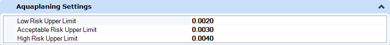
Aquaplaning Settings
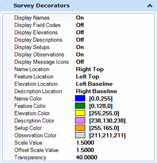
Survey Decorators
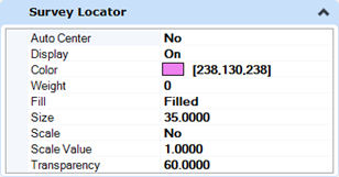
Survey Locator
Survey Maximum Error Ellipse

Survey Medium Error Ellipse

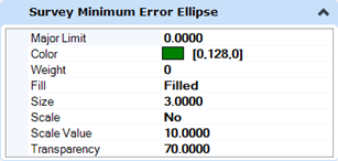
Survey Minimum Error Ellipse
Superelevation Settings
When the superelevation components are drawn into the design file, these two options allow the user to specify whether they are to be drawn as Color Shaded Fill or Boundary Only.
|
Option |
Description |
|
Color Shaded Fill |
Color Shaded Fill Color fills superelevation lanes AFTER calculations are complete. The coloring is hard-coded based on the cross slope: slope < -10% =blue -10% <= slope <= -0.5% = Calculated color between green and blue -0.5% < slope < 0.5% = white 0.5% <= slope <= 10% = Calculated color between red and yellow slope > 10% = dark red Based on the side of road, the colors flip. In addition to setting this option, the View Attribute for Fill must also be toggled on. |
|
Boundaries Only |
In this option, only the outside boundary of each lane is displayed and can be selected. |
|
None |
No superelevation lanes / edit handlers are displayed, however, they are still in the file. To display them, set to one of the other two options. |