Spiral between Elements
 Used to construct a spiral (or
spirals) between two base elements that determine tangency.
Used to construct a spiral (or
spirals) between two base elements that determine tangency.
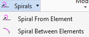
You can access this tool from the following:
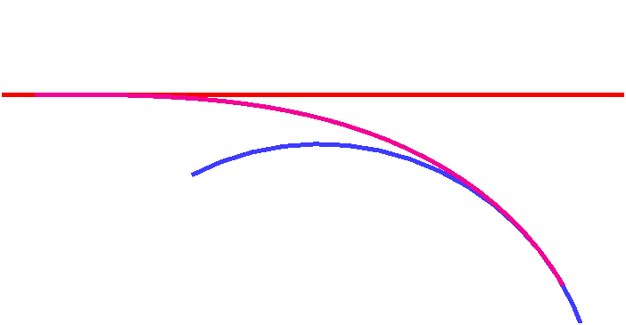
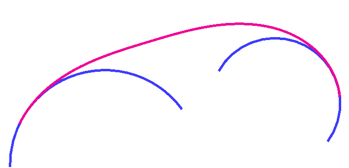
Spiral Between Elements constructs a spiral (or spirals) between two base elements that determine tangency. Dependent on the configuration of the base elements, there may be:
A line and an arc
Two arcs where one arc is contained entirely within the circle of the other arc
This tool provides clothoid spirals only. Other spiral-like transitions, such as Bloss, etc., are not supported.

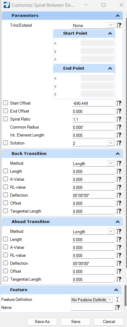
Spiral Between Element Dialog

Operation
Any of the inputs can be locked in the dialog at any time. Locking some values may limit or otherwise affect the other values.
You may lock one of the spiral lengths, but not both. When one spiral is locked, then the length of the second will adjust to produce the compound or reverse spiral. If both spirals are locked, then the effect is same as if both were unlocked. That is, the two spirals are made of equal length to fit the solution.
Common Radius is used only on compound spirals. If a common radius is specified, then the reverse options will be unavailable. When common radius is defined then the first spiral will transition from arc radius 1 to common radius and the second spiral will transition from common radius to arc 2.
-
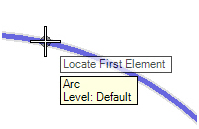
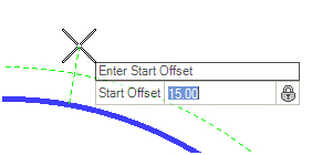
Select the first base element to construct the spiral from. Use a left-click to accept.
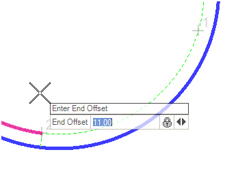
-
Select the second element and offset from second element. Note that, when setting the offset, there are some gray numbers, indicating alternate solutions. Moving the cursor near one of the numbers will select different solutions for the spiral construction. There might be up to four solutions depending on the configuration of the base elements.
-
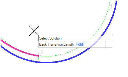
If the base element configuration dictates a double or reverse spiral, then you will get an additional prompt for transition length. If the default is accepted, then the two spirals will have equal length. Note that you get another chance at this prompt to choose one of the four solutions.
-
Notice the toggle arrows to the right of this prompt. Using the right arrow key, you can toggle through the other options on the dialog for input at this prompt. Other inputs available here are:
-
-
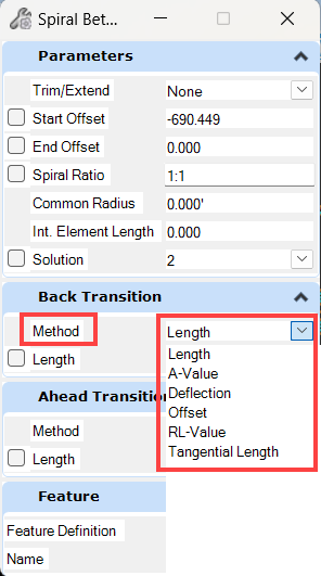
Options: The spiral is defined as a length above. As an alternative, your may define the spiral by radius and one of the following by changing the method on dialog.
-
Length (Shown above) the length of the spiral
-
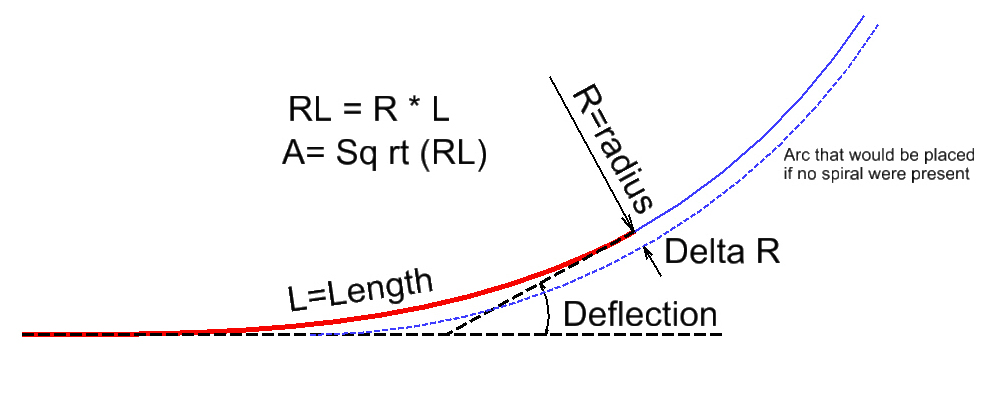
RL-Value the spiral is defined by a parameter equal to the radius multiplied by length
-
A-Value RL values can be quite large, so in some jurisdictions the A value is used; A-value is equal to the square root of RL
-
Deflection sometimes called spiral angle or theta angle; this is the deflection at the spiral point of intersection
-
Offset - also called throw or spiral offset (identified as Delta R in the image); this is the offset from the simple curve that would exist without a spiral to the same curve after a spiral is introduced.
- Tangential Length- This method enables creating spirals defined by an tangent length.
-
Use of ALT key
During the operation of the command, the ALT key can be used to switch between alternate solutions. When the onscreen dynamics show the (up to) four solutions, pressing the ALT key on keyboard will switch between the alternates.
Dialog Customization
Right-click on the dialog to customize it for specific tasks or user preferences.
Ability to Customize Dialog
Manipulators

Manipulators are available for:
Properties
The Arc Between Elements rule data is also accessible in the properties. The properties shown below are editable.
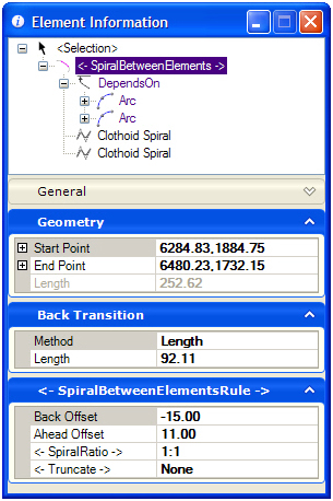
Editable Properties
Each spiral (if double spiral construct) will have the following read-only properties that can be useful for review by the civil designer.
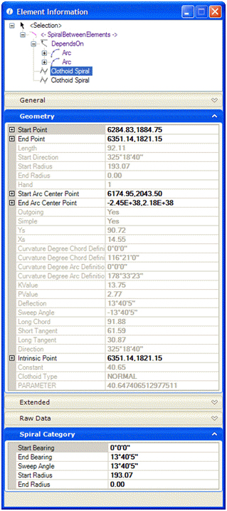
Read-only Properties