Create Connecting Node
Ribbon: Track > Rail Topology > Create Connecting Node
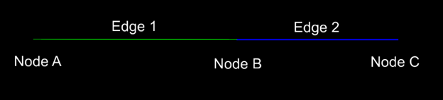
A Connecting Node will add a geometry to an existing Topology model. In a case where there is no turnout connecting two geometries, a Connecting Node can add main- or branch-geometry to the Topology model without having a turnout object present at the geometry intersection point. Another scenario is when two geometries ends and starts at the same point, a Connecting Node can join the two.
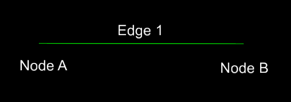
Geometry (1) and (2) will share the same Node (B). Node (B) for Geometry (1) will change type from a "Start/End" type of Node to a "Connecting" type Node.
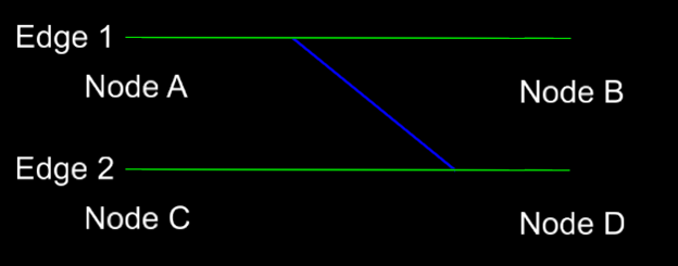
In a case where, for example, a crossover should be added to two already existing Topologies, the crossover needs to be connected to both existing Topologies, in two steps.
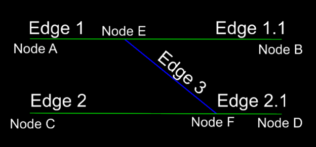
The picture below shows two main lines, which already are part of Topology models. Adding the crossover needs to be done by first creating a Topology of the crossover, following the workflow of adding a geometry. As a second step, the crossover needs to be joined with the other main line. Same workflow should be used to add the crossover to Edge 1 and Edge 2.
Create Connecting Node Dialog
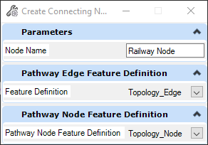
Node Name: Connecting Nodes's name prefix, which will be pre-pended with an incremented integer number.
Pathway Edge Feature Definition: Topology Edge Feature Definition
Pathway Node Feature Definition: Topology Node Feature Definition
- Open the Dgn model containing the Topology model.
- Run the Create Connecting Node command.
- Select a Feature Definition for the Edges and Nodes.
- (optional) Key-in a Node Name.
- Select an existing Topology model.
- Select geometry, which should be added to previously selected Topology.
- (optional) Right Click to change direction of the geometry to be added.
- Accept direction.
- Accept selected geometry.
- Open the Dgn model containing the Topology model.
- Run the Create Connecting Node command.
- Select a Feature Definition for the Edges and Nodes.
- (optional) Key-in a Node Name.
- Select an existing Topology model (1)
- Select geometry (2), which should be added to previously (1) selected Topology
- (optional) Right Click to change direction of the geometry (2) to be added.
- Accept direction.
- Accept selected geometry (2)
- Select the other existing geometry (3), also connecting the geometry (2)
- Accept selected geometry (2)
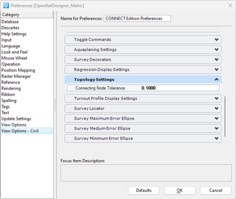
Defining the Connecting Node Tolerance
Adding a geometry to an existing geometry, if there is a gap between geometries, the User Preference: View Options - Civil -> Topology: Connecting Node Tolerance needs to be set to a value bigger than the gap between the geometries.