Support Drawing Template Creation
A default drawing production template named OPSE_DrawingProduction.dgn is included with the OpenPlant Support Engineering install. This drawing is stored in the following location:
C:\ProgramData\Bentley\CONNECT Edition\OpenPlant Support Engineering\Configuration\Workspaces\WorkSpace\WorkSets\%Workset%\Standards\Seed\Others
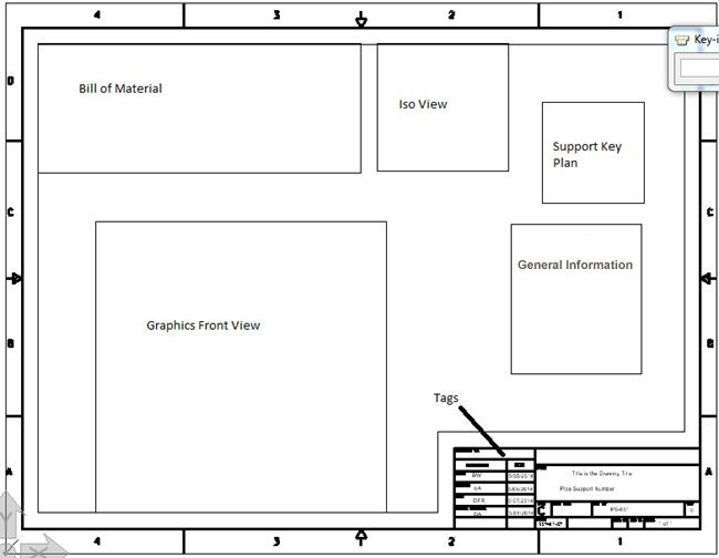
By default, the template drawing contains the following areas:
- Constant Area: Constant text and images that need to appear on every support drawing is part of this constant area e.g. Company Logo and boundary and so on. All the constant graphics and text could be added in template using MicroStation commands.
- Dynamic Area: There are many dynamic areas that need to be defined in the template where program will output information from the actual model. These dynamic areas are defined using a name and a rectangular boundary. This boundary defines the limit for the drawing production procedure to fit in the information. Whereas the name defined what information need to be placed where.
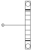
Below is the snapshot of the template drawing shipped with OpenPlant Support Engineering with the default areas. These areas are visible if DPTemplate Layer is switched ON.
Customizing the Support Drawing Template
While the template creation options allow you to define the different areas in a Support Drawing, the Project Dashboard lets you customize different project parameters for the support drawing template:
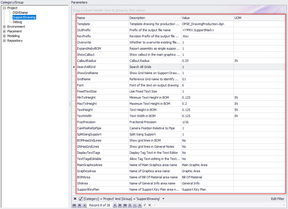
The Support Drawing Parameters section lets you define basic default project values for the drawing, such as the Project Name, Template, Project Status, etc. as well as control the look and feel of how the support drawing will appear. Parameters such as Font, Min/Max text height, whether the BOM will have grid lines etc. You can also configure whether predefined assemblies appear as a single assembly component or explode the information into individual components in the output drawing.
As you can note, you can also determine the name value for the different areas included in the support drawing. Once the fields in this section are defined and saved, the values are used when a support drawing is created.
Support Drawing Camera Position Parameter
CamPosReltoPipe =
Using the example model below shown in a top view, there is a clamp placed on a pipe running in the Y direction:
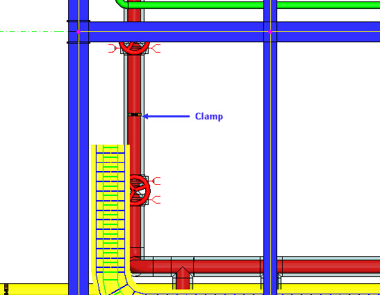
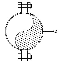
When CamPosReltoPipe = 1 (default setting) in the Project Dashboard, when a support drawing is generated, a left view of this clamp relative to the pipe direction would display as shown:
When CamPosReltoPipe = 0, the left view of the clamp in relation to the model displays as follows:
Once the parameter has been modified and saved in the Project Dashboard, the OpenPlant Model will need to be refreshed and a new Support Drawing generated for the change to take place.
Key Plan (Grid Lines)
OpenPlant Modeler provides tools to create a grid lines to aid in the layout of a model and the position of elements in the model. If a grid line model has been created in OpenPlant Modeler, you have the ability to attach this model as a reference and view/use it in OpenPlant Support Engineering .
In the Support Drawing parameters section shown above the following parameters determine how the grid(s) is used when creating a Key Plan for the support component:
| Parameter Name | Value |
|---|---|
| SearchAllGrid |
Value = 1: If multiple grids are defined in the model, then OPSE will search all of the grids and determine which grid line is closest to the component and reference that in the Key Plan. It is recommended the ShowGridName option (below) is used when searching multiple grids. Value = 0: OPSE will search the main default grid (which is defined in the GridName field below and use that grid for the Key Plan. |
| ShowGridName |
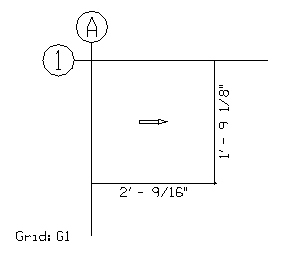
Value = 1: Will show the grid name when creating the Key Plan. (See Grid: G1 in above image) Value = 0: Grid name will not display on the Key Plan. |
| GridName |
This defines the default grid which will be
searched first whenever determining the closes grid line for the Key Plan. If
the SearchAllGrid option is turned off this will be the grid referenced for the
Key Plan.
|