Assembly Manager
The Assembly Manager lets you to create, edit, and insert assemblies into a drawing. Assemblies can consist of a complete drawing of a Process Line or just a section of a Process Line.

The dialog provides an interface to create, edit, and insert assemblies into a drawing. Assembly Locations are shown in the left pane and the assembly image in the right. Commands display in both the menu system and as toolbars. A context menu that mimics the available toolbar and menu commands is displayed when you right-click on a selection within the navigation tree.

| Setting | Description |
|---|---|
| Assemblies Menu |
The following options are available: New Assembly: Launches the Assembly Creation Wizard which guides you through the assembly creation process. New Group: Allows you to create new sub-directories under any of the Rename: Allows you to rename the selected assembly. User Assembly Path: Lets you add a root directory where user assemblies can be created and stored. If you have existing assemblies stored in the directory, they will be available for placement as well. Delete: Deletes the selected assembly. Insert: Provides two insertion options:
|
| Edit Menu | The Cut , Copy and Paste options operate in a similar manner to Windows Explorer. You can use these options to move assemblies from one location to another, or delete them completely. |
| View Menu | The following options are available:
Highlight: When enabled, this option highlights the selected assembly component in the preview pane. |
Save Assembly

|
Click this toolbar icon to save any changes to an assembly. |
| Assembly Locations |
The assembly locations are listed in the left pane and contain the following default options. Assemblies may be further categorized under each of these locations by creating new directories using the New Group option. |
| Search | Select an assembly name from the drop down list, or type a name of an assembly in the search field and press the arrow button to the right to search. If found the assembly is displayed in the preview pane. |
| Preview | A preview of the selected assembly is displayed in the pane to the right of the assembly tree. If the Highlight option is selected, as you click on each component in the assembly tree, its graphical image will be highlighted in preview pane. |
| Insert |
Press this button to insert the assembly in the drawing using either of the following options: As Assembly: Inserts the assembly as a complete assembly. When inserted like this, if you click on a component on the assembly after it is inserted, it will select the complete assembly, making it easier to copy or move the complete assembly if required. If you click on the component twice, then just the component is highlighted. Individual Components: When inserted as components, if you select a component on the assembly after it has been inserted, then only that component is selected, and not the whole assembly. |
| Details | If an individual assembly component is selected under an assembly root directory, this button displays the same component properties available in the Properties dialog, allowing the user to make any necessary changes. |
Inserting an Assembly
When you select an assembly and click the insert button, the Modify Assembly Tags dialog displays allow you to view the Tag Number and component property information on the group of components that make up the assembly and make any changes before placing the assembly.
Regular inline assembly limitations:
- A bypass assembly must contain only in-run components, such as valves. Angle, three and four way in runs are not allowed. Data changes, such as reducers, are not allowed. Pipe runs are not allowed.
- An inline assembly's components must be collinear with the origin.
- An inline assembly must be inserted into an existing pipe run.
- For inline assembly insertion rotation to work properly, the in run components must be horizontal inside the assembly.
Inline assembly with bypass limitations:
- An inline assembly with bypass must contain one bypass line, whose ends form branches of a main run(s).
- An inline assembly with bypass may not contain page connectors or equipment.
- An inline assembly with bypass must contain main pipe run(s) along with the bypass pipe run(s).
- The inline assembly with bypass main pipe run(s) must be collinear with the origin.
- The inline assembly with bypass main pipe run(s) may only have 1 section, i.e. simple straight run(s).
- An inline assembly with bypass does not have to contain a pipeline.
- An inline assembly with bypass must be inserted into an existing pipe run.
- For inline assembly with bypass insertion rotation to work properly, the main run(s) must be horizontal inside the assembly. NOTE: the first release will NOT support placing bypass into vertical run segment!
Editing an Assembly
The components in an assembly may be edited either by
using the Assembly Manager, or by clicking on an assembly component in the
drawing and using the Element Info dialog to edit. If you edit an assembly
component using the Element Info dialog, then the changes will apply to that
single instance of the assembly. When using the Assembly Manager to edit
assembly components, click the
Save Assembly
option to permanently save the
changes to the assembly, thus changing the definition of the assembly.
Right-Click Menu
When you right-click on a directory, or assembly in the assemblies section, the following popup menu displays with quick access to most of the options available from the Assembly Manager's menu system.
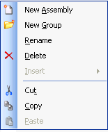
Certain options are enabled only when assemblies are selected.
Drop Assembly
This option displays when you select an existing assembly in the drawing. This will drop the relationship between the components of the assembly. Once the components have been dropped, they will no longer be considered an assembly and can be selected and edited as individual components.