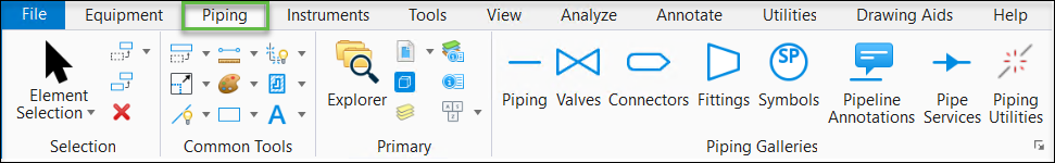
Piping Gallery
Used to place pre-defined pipe symbols in the drawing.
Accessed from:
The following gallery displays which can be left floating or docked to the drawing area.
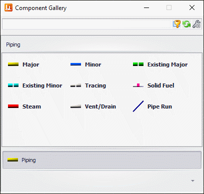
Pipe Lines
When placing one of the pipe line options, prior to placing it in the drawing, OpenPlant PID displays the Pipe Line Tag Creation dialog prompting you to assign a tag number to the pipeline and a name for the pipe run to be placed.
OpenPlant PID major and minor pipelines are unique in that they are intelligent; when a major process pipe is created and a run placed, OpenPlant PID automatically associates information (e.g., run number, size, to/from information, etc.) with that pipe. Data associated with a pipe can be viewed or edited by selecting Element Info. Each OpenPlant PID line type is drawn on a different level according to the Element Template.
You now have the ability to configure a string list on the Number property of Pipelines so that if any constituent property of a tag is changed from Standard Preferences, the software will reset the next prompted Number to the next available number in the Placement dialog
| Setting | Description |
|---|---|
| Pipelines | All of the Pipeline options in this taskbar are drawn using MicroStation lines by default. Each Pipeline type is drawn on a different level which is defined in the Element Template dialog. Existing process pipes display as phantoms to distinguish between the line types. When a Pipeline option is selected, the Pipe Line Tag Creation dialog displays prompting you to create a tag number for the Pipeline, and a name for the Pipe run that will accompany it. You will also be able to define the initial process properties for the Pipeline as well as component properties for the pipe run. ( See note above regarding the Pipe Line Tag Creation dialog) |
| Pipe Run |
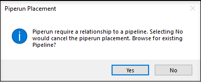
Creates a pipe run off of an existing pipe line. When a pipe run is run off of an existing Pipeline, it will inherit the Pipeline's properties and becomes a child of the pipeline. Note: If a pipe run
is not routed from an existing pipeline the following message displays:
Click
Yes to browse for existing pipeline and
click
NO
to cancel the placement process.
Once a Pipe Run has been routed, the Pipe Run Properties dialog displays prompting you to create a name for the Pipe run and define initial component properties such as Size, Weight, Wall Thickness, etc. ( See note above regarding the Pipe Line Tag Creation dialog) |
Pipe Runs
You can draw a pipe run and assign it to a pipeline without making a physical connection to the pipeline in the drawing or you can place pipe run in conjunction with existing pipe lines. The pipe run inherits the pipe line's base properties. When selecting the Pipe Run option, the Place Pipe Run dialog displays allowing you to determine the flow direction for the run as well as control the display of flow arrows and their locations. After the run is placed, the Pipe Run Properties dialog displays prompting you to define the tag number and component properties for the pipe run.
AutoRouting
Pipe runs can be routed either manually, where you select a start point and manually route each point in the line to its endpoint, or by using the Auto-Router method, used when you are routing a run between existing components.
Click here for additional information on the Auto-Router functionality.
Jumpers
If you place a pipeline/run which intersects with another pipeline, a jumper symbol will automatically be placed at the point of intersection. The jumper will display as a break in the line which crosses over the existing line.
Extend Run
If you are placing a pipe run and select the end of an existing run as the start point, the Extend Run dialog displays prompting with options to either extend the existing run, or create a new run. If a new run option is selected, you will be prompted with the Run Properties dialog once the routing procedure is completed.