Connectors Gallery
Used to place Pipe Run Page connectors as well as various connector symbols in the drawing.
Accessed from:

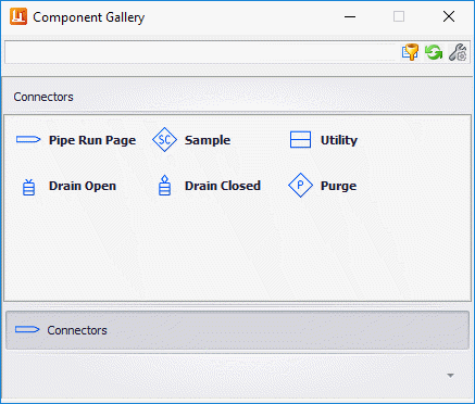
The following gallery displays which can be left floating or docked to the drawing area.
It displays a list of connector symbols which can be used to display connections on the current drawing. Pipe Run Page connectors are used to identify processes going from one drawing to another.
| Setting | Description | |
|---|---|---|
| Pipe Run Page | These connectors are designed to link process lines from one sheet to another. It displays the Connectors Options dialog allowing you to define the links for the connector. The type of connector (On/Off page) is determined during the placement process. | Because OpenPlant PID is integrated with the iModel Hub, connectors can be linked across multiple drawings. Changes are synced with the iModel either manually, or they can be setup to sync automatically with the opening or closing of a drawing. The options for this are available in the Tools ribbon. |
| Miscellaneous Connectors | The remaining connectors in the taskbar are placed using the mouse to drag and drop the symbol to the desired location. These are not designed to link between drawings. |
When placing a Pipe Run Page connector, there are a number of placement options to choose from as shown:
Place a Connector on a Pipeline
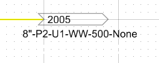
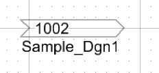
When placing a new Pipe Run Page connector, you can place the connector on an existing pipeline instead of in space. When this is done, the page connector inherits the properties of the pipeline and the connector annotation reflects the line properties as shown below.
The only prerequisite for using this option is you must have an existing pipeline in the active drawing and you will need to select the Connector Direction. Otherwise, the placement procedure is the same as placing an unlinked connector.
Place and link a connector on a Pipeline
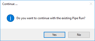
If you click Yes, you will be prompted to pick points to continue the pipe run on the target drawing. When finished, the connector is annotated with the Model Name of the linked connector.
If you select No, then the connector is placed without any connection to the matching connectors pipe run and only the directional annotation is placed.
To view how the components are linked, right-click and select Properties from the popup menu:
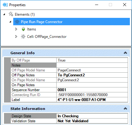
- Notes: A common note which can be associated with both connectors can be defined here and placed as annotation for each connector.
- Off Page Notes: Can be used to place a note identifying the drawing the On Page connector is placed on.
- On Page Notes: Can be used to place a note identifying the drawing the Off Page connector is placed on.
The Off Page Model Name displays the name of the model the Off page connector is coming off of.
To define a sequence number, either enter a number directly into the field, or click the arrow button in the field to display the control shown below. This control allows you to select the next available number for the sequence or increment the current number by the amount shown in the Increment By field. The Maximum button sets the tag number one number above the current highest number used. (For example, if the current highest tag number used is P-104, then the Maximum tag number will be set to P-105.)
Follow Page Connector
This option is accessed from the context menu which displays when you right-click on a connector. The command will take property changes made to a pipeline/piperun associated with a page connector on a source document, and automatically follow the link. When the command is executed, the target drawing containing the linked connector will be launched opened and it will zoom into the matching connector.
When the current drawing is closed, the drawing will sync the changes with the iModel. Thus, when the connecting drawing is opened, it is synced automatically with the iModel and updated with any changes.
Link two existing connectors
If you have two existing connectors (an Off Page and an On Page) residing in different drawings, you have the ability to right-click on a connector in one drawing and link it to the matching connector in the other. Initially, the Connectors Options dialog displays with a list of .dgn files displayed. You can either select a file from the list, or use the Browse option to navigate to a directory where the desired file is stored. As you select a file from the list, a list of Available Connectors displays for that file. Click on an available connector and the annotation will be updated in both drawings to include the directional annotation for the linked connector.
Place an Unconnected/Unlinked Connector
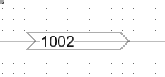
A connector is placed in space on a drawing without any connections or links to any pipelines or other existing page connectors. When placed, annotation denoting only the sequence number is displayed with the connector as shown:
After the connector is placed, the Place Component dialog displays prompting you to place a pipeline attached to the connector. If no pipeline is required, Cancel out of the dialog.
Link to an Existing Connector
Moving Connectors
Connectors that have been placed can be moved using the drag and drop method. Select the connector to displays its Edit Handles and use the handles to drag the connector to the desired location. If the connector is connected to a pipeline, then the pipeline is rerouted to maintain its connection to the Pipe Run Page connector.