Hidden Line Options
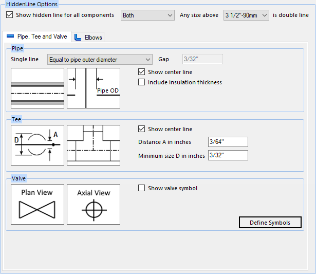
The OpenPlant Orthographics Manager separately generates 2D Hidden drawings that are generated by HSR (Hidden Surface Removal) processor. You can customize the Hidden drawing using the Hidden Line Options page shown below.
Accessed by selecting the Hidden Line Options node in the Settings interface.
The Hidden drawings will be written in an OpenPlant (DGN) format with the Level options defined.
Define the properties per the fields described below and Save the changes.
The Close icon closes the Project Settings interface, so make sure your changes are saved. You will be prompted to save them it you haven't already.
The Load Defaults icon in the main Settings interface will return the settings of the options page to their original values.
Selective Line Display
Use the following options to determine which type of Hidden Line representation will be used:
| Setting | Description |
|---|---|
| Show Hidden line for all components |
This option determines whether hidden lines will be created or not. If this option is disabled, then the hidden elements and levels will not be created. |
| Single Line | Pipe lines are displayed in Single line representation. |
| Double Line | All pipe lines are displayed in double line representation. |
| Both |
Both Single and Double line types are used according to the pipe size. When this option is selected, it is used in conjunction with the following option: |
Pipe and Tee and Valve Options
The following options apply to the Pipe and Tee tab of the Hidden Line Options page (see image above):
The options in the Pipe, Tee and Valve tab define how those types of components will display in the Hidden Line drawings. Use the bitmap images for references when defining the settings. For some settings, the images are updated dynamically so you can see how they will be displayed.
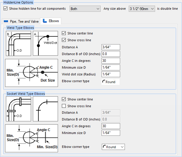
Elbows Options
The options in the Elbows tab define how the Welded and Socket Welded elbows will display in the Hidden Line drawings. Use the bitmap images for references when defining the settings. For some settings, the images are updated dynamically so you can see how they will be displayed.
| Setting | Description |
|---|---|
| Weld Type Elbows |
Show Center Line: Toggles
the center line On/Off for the elbow.
Show Cross Line: Toggles whether the
cross line (extension of the center line to where it would intersect) is
displayed on pipe bends.
Distance A: Defines the distance beyond the intersection point the cross line will extend for single line representation. Distance B of OD: Defines the distance beyond the intersection point the cross line will extend for double line representation. The value of this option is the scale factor of the pipe's outer diameter. Angle C in degrees: It is the opening angle when the elbow goes upwards. The default value is 30 degree. Minimum size D: Minimum size for a non 90 Degree Weld Type Elbow. Weld dot size: If a Weld dot is used as a weld symbol, this option defines the size of the dot. Elbow corner type: Only Round corner type is available for the Weld Type Elbow. |
| Socket Weld Elbows |
Show Center Line: Toggles the center
line On/Off for the elbow.
Show Cross Line: Toggles
whether the cross line (extension of the center line to where it would
intersect) is displayed on pipe bends.
Distance A: Defines the distance beyond the intersection point the cross line will extend for single line representation. Distance B of OD: Defines the distance beyond the intersection point the cross line will extend for double line representation. The value of this option is the scale factor of the pipe's outer diameter. Angle C in degrees: It is the opening angle when the elbow goes upwards. The default value is 30 degree. Minimum size D: Minimum size for a non 90 Degree Weld Type Elbow. Weld dot size (Radius): If a Weld dot is used as a weld symbol, this option defines the size of the dot. Elbow corner type: Defines whether the elbow corner is displayed as Round or Square. |