The Distance page provides options for you to define the
distance for the dimension levels for external pipe, pipe elevation, equipment
and structure.
Accessed by selecting the
Outside > Distance node in the
Settings interface.
Define the properties per the fields described below and
Save the changes.
The Close icon closes the Project Settings interface, so
make sure your changes are saved. You will be prompted to save them it you
haven't already.
The Load Defaults icon in the main
Settings interface will return the settings of the options
page to their original values.
| Setting | Description |
|---|
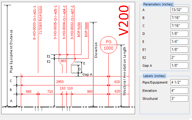
| Distance Parameters
|
A: The distance of the first level dimension, which
are for the pipe, equipment and structure dimensions.
- B: The distance of
the second level dimension, which are equipment and structure dimensions.
- C: The distance of
the third level dimension, which is global dimension.
- D: Reference the
bitmap image to define the distance here.
- E: Reference the
bitmap image to define the distance here.
- E1: If there are
several elevation texts to point to other pipes in the nearby area, the leader
lines of the elevation text should overlap. So there needs to be a gap distance
defined among these leader lines. The default is 1 mm.
- E2: The distance
between the starting leader lines of the elevation text, which is the nearest
leader line from the view frame. The default is 50 mm.
- Gap A: Reference
the bitmap image to define the distance here.
|
| Labels
|
Pipe/Equipment: It is the distance of
the label of the pipes or equipments.
Elevation: If the adjacent pipes outside
the view have the same elevation, they can be grouped and be pointed by the
elevation leader line as bottom of pipe/elevation text. Refer to the Tag
Numbers > External View topic for additional information.
Structural: It is for the structure
column annotation distance.
|