Levels
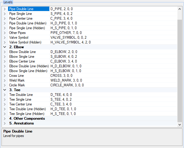
When Orthographics Manager processes a 3D model, it creates a Hidden drawing from the model. As with most models, there are several Levels where the different sizes and types of components or annotations are placed. The Levels options page lets you define the color, size and weight of the lines used in each level.
Accessed by selecting the Levels node in the Settings interface.
Define the properties per the fields described below and Save the changes.
The Close icon closes the Project Settings interface, so make sure your changes are saved. You will be prompted to save them it you haven't already.
The Load Defaults icon in the main Settings interface will return the settings of the options page to their original values.
To modify any of these properties, expand the arrow button to the left of a level to display as shown below:
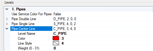
The following properties are defined for each level of the drawing.
| Setting | Description |
|---|---|
| Level Name | Displays the name of the level. The level name can be change in the main property field. |
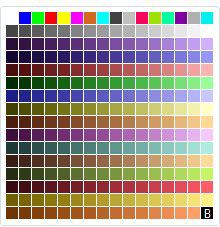
| Color | Click in the Color field to display an arrow icon which displays a Color Table to select a color for the line type. |
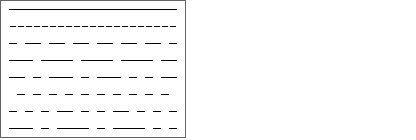
| Line Style | Click in the field to display an arrow which displays a list of line styles to choose from: |
| Line Weight | Enter a line weight directly into the field. Line weight values range from (0-31). |
| Hidden Lines |
Levels denoting hidden lines are defined by appending (Hidden) to the line type in the left column and prefixing an H to the Level name in the settings field as shown below: H_D_PIPE,0,1,0 |
| Save | Save the changes made to any of the fields. This button only enables when a change is made. |
| Close | Closes the Project Settings interface. If you haven't saved the changes, you will be prompted with a message dialog to do so before closing the interface. |