Hatch Marks
The Hatch Marks page lets you define how Hatch Marks, Slope Marks and Flow Marks are displayed.
Accessed by selecting the Annotations > Hatch Marks node in the Settings interface.
There are 2 types of pipes, one is a single pipe and the other is a double pipe as discussed in selecting pipeline mode. This hatching mark is created automatically, if the view plane of 3D view volume in the model clips pipes. For example, if the pipe passes by view plane to the upper view volume from the lower view volume, this mark is created with the same size of the pipe.

Define the properties per the fields described below and Save the changes.
The Close icon closes the Project Settings interface, so make sure your changes are saved. You will be prompted to save them it you haven't already.
The Load Defaults icon in the main Settings interface will return the settings of the options page to their original values.
Hatching Mark Options
| Setting | Description |
|---|---|
| Hatching Mark Symbols |
The following bitmap options are available from the Single Mark and Double Mark drop down lists: |
| Mark Display | |
| Any size Above | When the mark display option is set to both, then any pipe size above the size defined from this drop down list uses a Double Mark hatch. |
| Minimum circle diameter | Sets the minimum circle diameter for the hatch mark. |
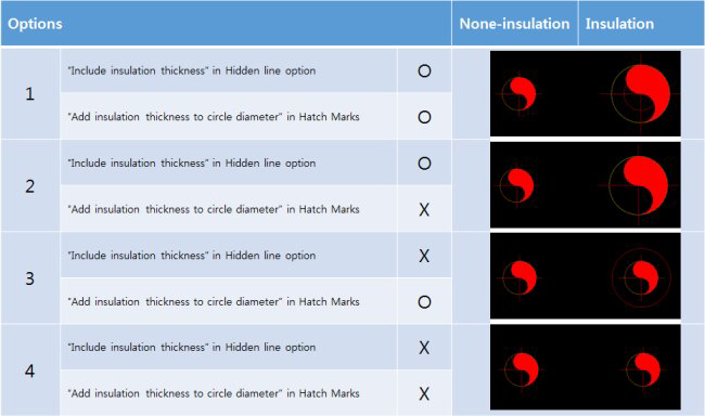
| Add insulation thickness to circle diameter |

Slope Marks Options
Flow Marks Options
| Setting | Description |
|---|---|
| Leader | |
| Arrow Type | Select an Arrow type from the drop down list.
The User Defined option displays the Select User Defined Arrow dialog letting you select an arrow symbol from a cell library. |
| Mark Display |