Place Weld Symbol
 Used to place a callout for a
selected component in the support drawing which corresponds to a BOM entry.
This can be used to either replace an existing callout which may have been
deleted, or used to move a previously placed callout.
Used to place a callout for a
selected component in the support drawing which corresponds to a BOM entry.
This can be used to either replace an existing callout which may have been
deleted, or used to move a previously placed callout.
Accessed from:
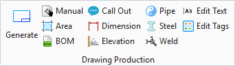
Drawing Production ribbon group
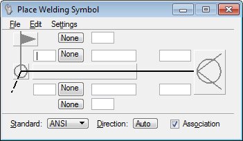
Displays the following dialog which is used to place a welding symbol in an extracted drawing.
Menus
Dialog Symbols
The dialog provides two sets of symbol and dimension data fields on either side of the reference line. The essential symbols are activated by feeding dimension data or included from the list.
Welding symbols
The skeleton of the welding symbol essentially includes major graphical elements.
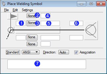
Weld Symbol Options
The dialog provides two sets of symbol options on either side of the reference line; one for choosing the weld, and another for the contour symbols (by default they all are set to None).
Click on the option menu to choose the graphic of appropriate to weld symbol.
| Setting | Description |
|---|---|
| Contour symbol option (Field 2) | Use the menu options list to choose one of the contour symbols from the list. |
| Basic weld symbol options (Field 3) | Use the menu options list to choose one of the contour symbols from the list. |
Weld Dimensions and Other Data
The rest of the fields, four on each side, accept alphanumeric data to be added in the welding symbol.