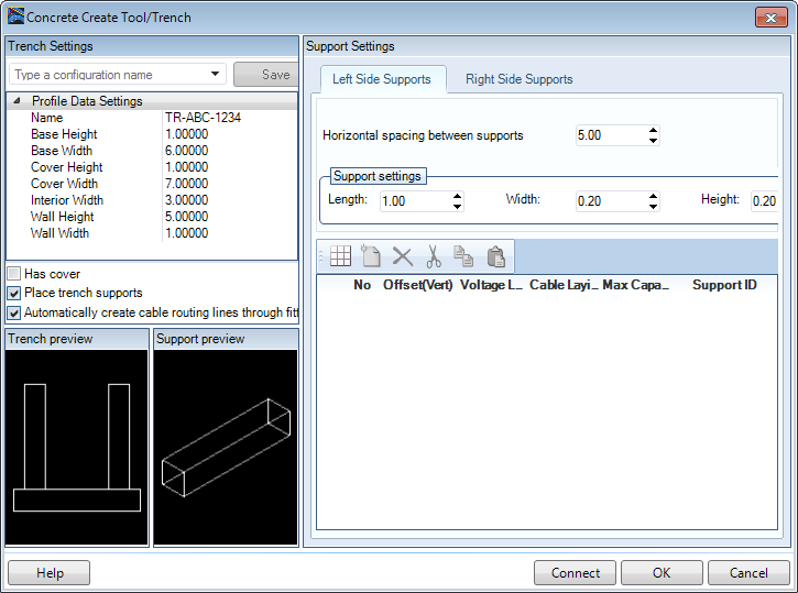
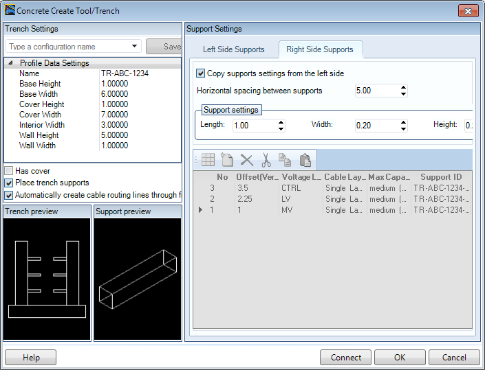
In the Trench Settings section set the following trench
parameters:
Name
Base Height
Base Width
Cover Height
Cover Width
Interior Width
Wall Height
Wall Thickness
Enable the
Automatically create cable routing lines through
fittings option. When enabled, the cable lines will continue
through any fittings in the trench such as elbows, tees etc. Otherwise you will
need to route them manually.
Optional: Enable the Has Cover option if the
trench is to be covered. When this option is enabled, the cover will display in
the Trench Preview.
Click the
Place Trench supports option to include
supports in the trench.
Settings for the trench supports are defined
in the Support Settings section of the dialog.
In the Support Left tab, click the
Setup Grid icon to define the support
layout.
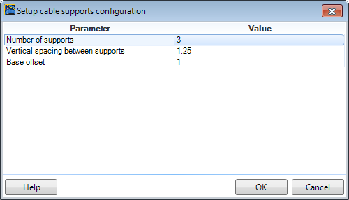
Define the support parameters as shown:
Click
OK to save the changes. Note the supports will
now display in the Trench Preview.
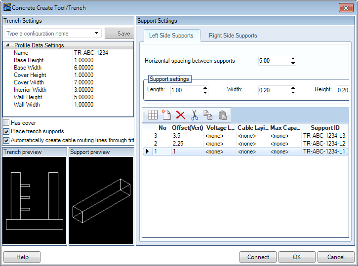
Set the distance for the Horizontal spacing between supports. For
example, in the image above, the group of supports will be spaced every 5'
along the length of the trench.
Define values for the support Length, Width and Height.
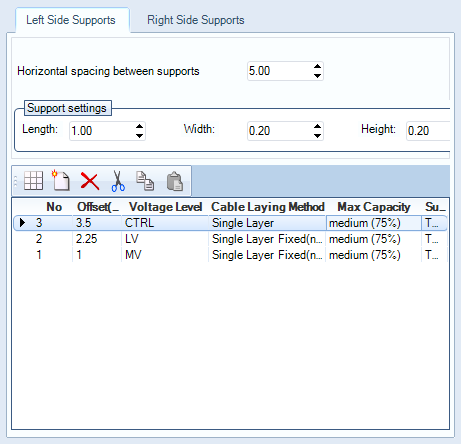
Define the support properties in the bottom pane. (Define the
Voltage Level, Cable Laying Method, and Max Capacity).
Click the Right Side Supports tab and check the
Copy Supports settings from the left side
option.
When enabled, this option will copy the support settings of the
left side and use them to place supports on the right side. Note that the
Trench Preview is updated to includes both sets of supports.
Press
OK to begin routing the trench.
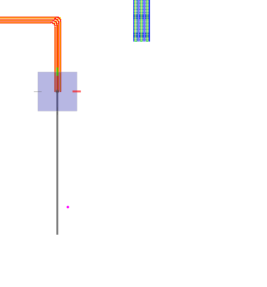
To start the trench placement at correct elevation, use snap and
offset AccuDraw functions to place the trench in reference to other components.
For example, to place raceway 50 feet away from the existing duct
bank, make point of origin at the existing duct bank and offset it for -50 feet
in Y direction.
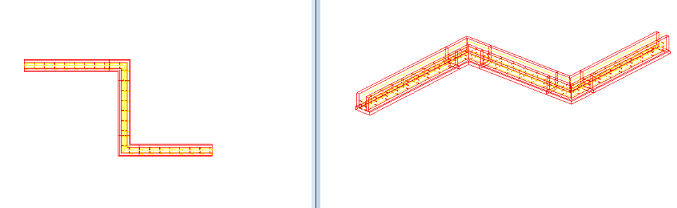
Click a data point to start the trench placement.
Place a 50 ft long section using AccuDraw.
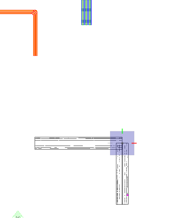
To make a 90 degrees horizontal bend simply move cursor towards
the bottom of the screen and place an additional 50 ft long section.
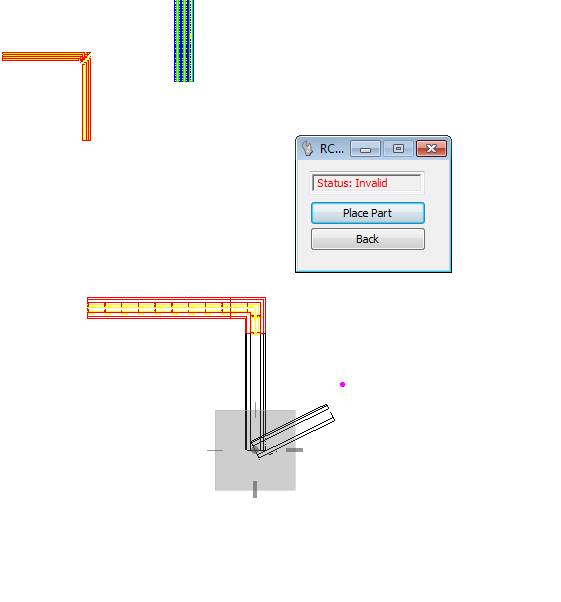
When placing a bend, if the angle cannot be made with a custom
bend, the Status will be view as Invalid and a bend will not be placed.
When you are finished routing, right-click to complete the
placement process.
 icon to define the support
layout.
icon to define the support
layout.