Raceway Generator
The Raceway Generator enables you to convert lines (Smart Lines) to raceways. Select a smartline in the model and click the icon to display the following dialog. This dialog contains the same fields available in the Raceway Router dialog, allowing you to define the Properties and Preferences for the new raceway.
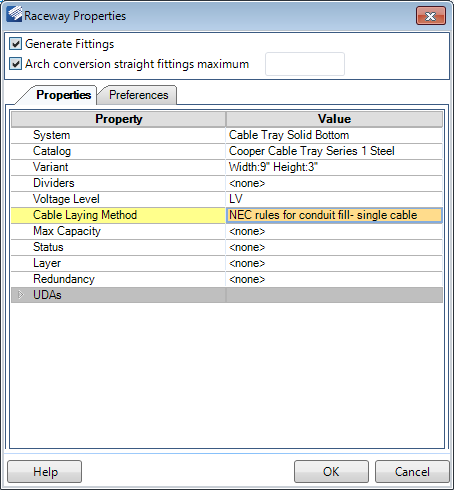
Properties
| Setting | Description |
|---|---|
| Generate Fittings | Enable this option to generates fittings where applicable on the route. If this option is disabled, only straight parts will be generated. |
| Arch conversion straight fittings maximum | When converting an arch into a raceway, this option lets you define the maximum number of raceway sections needed when converting the arch. As a general rule, the more straight sections used to convert the arch, the smoother the curve will be. |
| System | Select the type of Raceway system to be routed from the list. The following systems are included in the list: |
| Catalog | Select a catalog to use from the drop down list. |
| Variant | Define the size of the raceway/conduit component here. A cable tray size is defined as Width x Height while conduit is sized by the diameter. |
| Raceway Number | This number corresponds with the column and row of the raceway layout. For example Column A, Row 1 would have a Raceway Number of A1. |
| Dividers | If the raceway is to be divided into different sections, define a number of dividers to use here. |
| Divider/Section [%] (OPTIONAL) | If the raceway contains dividers, then these fields display letting you define the percentage of space each divided section will occupy. The number of fields which display is determined by the amount of sections the raceway is divided into. |
| Voltage Level | Select a voltage level from the drop down list: |
| Cable Laying Method | Select the method of laying the cable from the following list of options. This determines the routing configuration for the cable inside the raceway/conduit. |
| Max Capacity | The Max Capacity determines how much of the raceway/conduit area can be occupied with cables. |
| Status | Define the status for the raceway from the following list: |
| Layer | Select which layer the raceway will be modeled on from the drop down list. Raceway components have default layers assigned by default. If a layer is defined here, it acts as an override to the default layer. |
| Redundancy | When redundant systems need to be run, this option
allows you to label the system as such. By default, there are three redundancy
labels:
Additional Redundancy labels can be added in the Raceway Specifications/Raceway Categories tab of the Setup > Options dialog. |
| Accessories (Route) | This options allows you to define the spacing and size of the supports for the raceway/conduit system. Select an option from the drop down list. |
| Accessories (Raceway) | Select raceway accessories (dividers, brackets, covers etc.) to be included in the Raceway from the drop down list. |
Preferences
The preferences tab provides certain preferences you can define when placing the raceway components.
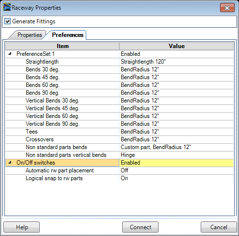
Below are descriptions for the fields which may display in the Preferences tab. The available preferences will vary depending on the type of raceway system selected.