How To Place an Assembly
-
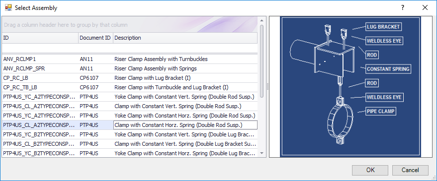
Select an Assembly type from the Assemblies toolbox.
The Select Assembly dialog displays.
- Select the desired assembly option from the list.
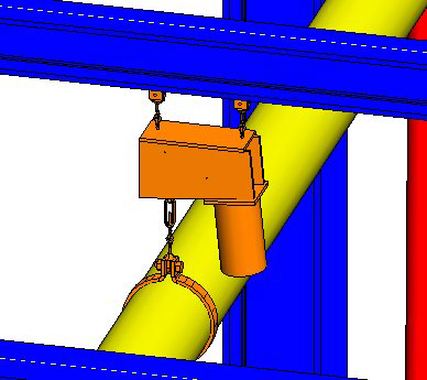
- Left-click the pipe component where the locator will be placed then left-click again to accept.
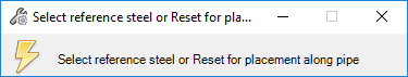
- Select the steel component the assembly will connect to.
- (Optional)
Press ESC to use the free placement method.
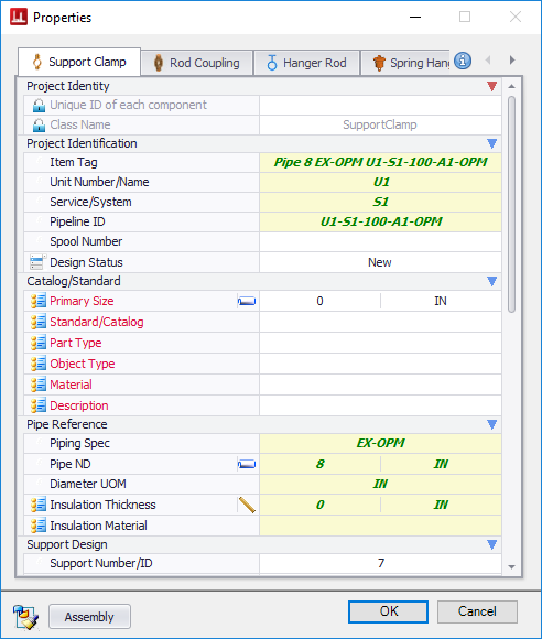
The Properties Dialog displays as a multi-tabbed dialog with a tab for each separate component in the assembly.
- Click on each tab and define a component type and size from the Catalog section.
- Define additional property values as necessary.
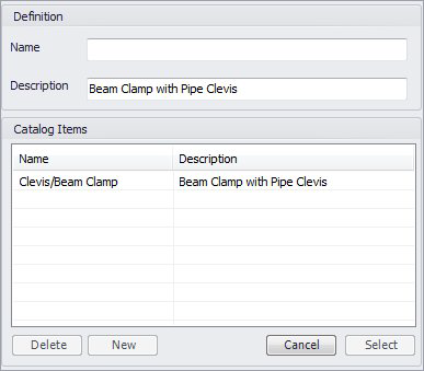
- Click the Assembly button to display the following dialog letting you name and save the assembly.
- Enter a name for the Assembly and click New to add it to the list. Click Select to return to the Properties dialog.
- When finished defining properties click OK.
Place Assembly without selecting the Steel
If you rejected the option to select the Steel in Step 4 of the procedure above, you will need to complete the placement of the assembly manually. The procedure below details how to do this.
-
Select an Assembly type from the Assemblies toolbox.
The Select Assembly dialog displays.
- Select the desired assembly option from the list.
- Left-click the pipe component where the locator will be placed then left-click again to accept.
-
Right-click to reject the option.
The Properties Dialog displays as a multi-tabbed dialog with a tab for each separate component in the assembly.
- Click on each tab and define a component type and size from the Catalog section.
- Define additional property values as necessary.
- (Optional) Define the Assembly as detailed in Steps 8 and 9 above.
- When finished defining properties click OK.
- Use the mouse to slide the locator along the pipe length to locate the final position, or you can use the Distance field in the Path Placement Dialog dialog to determine the position.
- Left-click two times to confirm the location.
- (Optional) For items using the stretch method to connect to a support structure, the Stretch Dialog displays.
- Either use the mouse to snap to a connect point, or enter a distance in the Stretch dialog.
- Left-click in the model to accept the distance.
- Use the Rotation fields in the Stretch dialog to define the correct orientation.
- When the Rotation is defined, left-click in the drawing area to complete the placement.