How To Place a Support Component
The following details a standard placement procedure which can be applied to most of the OpenPlant Modeler
Pipe Attachment components.
-
Select the Pipe Clamp option from the Catalog Pipe Attachments tool drawer.
Note: Remember the Tool Cabinet is divided into separate drawers each containing different types of supports.
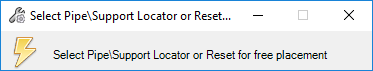
The following message displays:
-
Double-click a pipe to place the support on, or right-click (Reset) to place the support anywhere in the model.
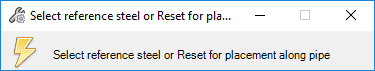
The following message prompts you to select a steel (structural) component to align the support with.
-
If you intend to connect the support to a support structure, select it now. Otherwise, click <ESC> to manually select a location along the pipe section.
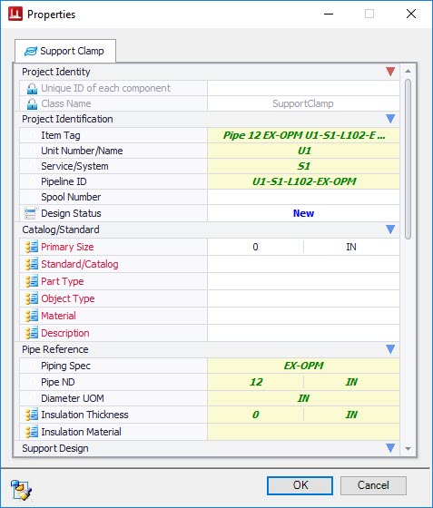
The Properties Dialog displays. This dialog is used to define the properties of the support component. The essential properties are marked in red.
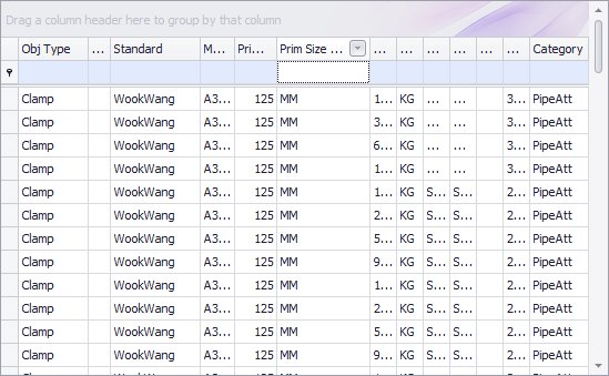
- Under the Catalog section, click in the field next to Standard/Catalog to display a grid providing a list of available Pipe Clamp components along with all of the catalog information for the components.
- Select a pipe clamp option from the grid. When you do, OpenPlant Modeler will populate the remaining essential fields using the catalog information of the selected clamp.
-
Define additional properties as desired and click OK.
If you selected a steel structure in Step 3, then the clamp will automatically be placed on the pipe aligned with the selected steel component.
- (Optional) If you opted to select the location for the support manually, then the clamp is affixed to the end of the cursor allowing you to slide it along the pipe to the correct placement location and the Path Placement Dialog displays providing fields to define distance, reference point and rotation of the component. You can either enter a distance value into the dialog, or use the mouse to pick the placement point for the component.
- (Optional) The Relative To drop down allows you to change the reference point from which the distance of the component is relative to. Three options are available:
- To rotate the clamp, enter a rotation into the field, or click the arrow button to display the following sliding scale which will dynamically rotate the clamp while you move the slider.
-
Once the clamp is placed and rotated correctly, click the Accept
 icon to complete the placement. (You can also click a data point (left-click) anywhere in the drawing area to accept the placement.)