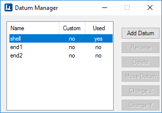
Datum Manager
This dialog displays the default datum points defined for the selected equipment component.

A Datum specifies a local coordinate system used to place Nozzles, Manways and Lugs on equipment. Default parametric components ship with built-in datum points but additional points can be added using this option if desired. Custom created equipment components, however, do not have pre-defined datum points, so you would need to use the Datum Manager to define at least one datum point before nozzles could be placed.
As you select a datum from the list in the Datum Manager, the datum is highlighted on the equipment component in the model.
| Setting | Description |
|---|---|
| Add Datum | Click this button follow the prompts to define a datum for the selected equipment component. |
| Rename | Click the Rename button and the datum point becomes editable. After renaming the point click Enter to save the name. |
| Delete | Click to delete the selected datum point. |
| Move Datum | This options allows you to move the origin point of the selected datum. After selecting this option, pick a point on the equipment component in the drawing to specify the new origin point for the datum. |
| Change Z | Allows you to change the direction of the Z axis defined for the datum point. Select the option and use the mouse to pick a point in the drawing to determine the direction. |
| Change Y | Allows you to change the direction of the Y axis defined for the datum point. Select the option and use the mouse to pick a point in the drawing to determine the direction. |
Defining Datums
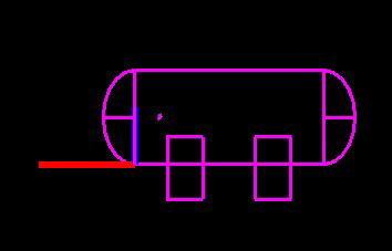
A datum point is defined by selecting a specified point on an equipment component, then defining the directions of the Z axis and Y axis which extend from the datum point. This is done by using the mouse to drag
An example of a datum is displayed below:
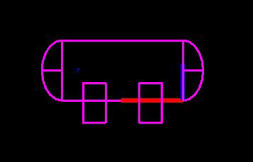
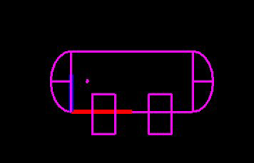
If you move the datum point, the direction of the Z and Y axis' remain the same as shown below: