Detail Style-Dimensioning - Views-Reference Points tab
Here you select the components for which you want to provide customized component dimensions in the view and you specify which basic dimensions are to appear. Basic settings for dimensioning (position etc.) are valid globally for all customized dimensions simultaneously, but here you can exclude certain components and dimensional chains.
Some settings on this dialog page can be found in the general description of the inputs for customized dimensions.
List of Dimensioning Groups
The following special dimensions may be added apart from the different component part groups for shapes and poly-plates, as well as a general group already described in the introduction:
| Special Dimensions | |
| Construction Axes | The existing construction axes (frame working area) of the view |
| Outer Edge Steel | Outer dimensions of steel construction related to the border axes |
| Diagonal Dimensions | Length and system dimensions for diagonal shapes |
| Manual Dimension Points | Manual dimensioning objects from the 3D model for overviews |
Special Forms of Dimensioning
Dimensioning of overviews differs a bit from dimensioning of groups with regard to possible reference points and position of dimension chains, especially if local areas are used.
For the dimension points (target points), however, nearly the same possibilities are available as at shapes in construction groups.
| Reference Connection | |
| Start View | Left resp. lower side of the overall view |
| Start Construction Axes | Extreme left resp. lower visible construction axis |
| Start Area | Left resp. lower side of the corresponding local area |
| Edge View | Side of the overall view which is situated next |
| Edge Construction Axes | Outer visible construction axis which is situated next |
| Edge Area | Side of the corresponding local area which is situated next |
| Component Part | Extreme left resp. lower dimension point which is used (self reference) |
| Next Construction Axis | The next visible construction axis in dimensioning direction |
| Additional Dimensions | |
| View | Outer edges of the overall view in dimensioning direction |
| Construction Axes | Utmost visible construction axes in dimensioning direction |
| View + Construction Axes | Outer edges and utmost visible construction axes in dimensioning direction |
| Area | Outer edgesof the corresponding local area in dimensioning direction |
| Position of Dimension Line (1st Field) (Only Inner Area) | |
| Middle | Geometrical center of the area |
| Middle Top / Left | A little bit above resp. left of the geometrical center of the area |
| Middle Bottom / Right | A little bit below resp. right of the geometrical center of the area |
| Half Top / Left | In the middle of the upper resp. left half of the area |
| Half Bottom / Right | In the middle of the lower resp. right half of the area |
| Top / Left | Above resp. left of the area |
| Bottom / Right | Below resp. right of the area |
| To Inside | Near area edge seen from the center of the overall view |
| To Outside | Far away area edge seen from the center of the overall view |
| Position of Dimension Line (2nd Field) | |
| Each Alignment | Dimensioning in each alignment towards the reference direction |
| Only if horizontal | Only dimensioning if part horizontal (parallel) towards reference direction |
| Only if vertical | Only dimensioning if part vertical (perpend.) towards reference direction |
| Only if orthogonal | Only dimensioning if part rectangular towards reference direction |
| Only if diagonal | Only dimensioning I fpart diagonal towards reference direction |
| Area Assignment (Only Inner Area) | |
| According to Belonging | Position of dimension chains in the belonging outer or inner area |
| Separate Outer Area | Position of dimension chains in the outer area, separate dimension chain for inner area |
| Common Outer Area | Position of dimension chains in the outer area, common dimensions |
Example
In the following figure, you see a simple example for dimensioning a view including construction axes display.
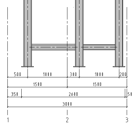
The first dimension chain from above shows the dimensioning of the shapes related to the construction axes, the second dimension chain shows the dimensioning of the construction axes and the third dimension chain shows the dimensioning of outer edge steel (2600). The overall dimension (3000) is measured over the outer axes.
Construction axes 1 and 3 could be hidden in the settings for overviews. In this case, they wouldn’t be dimensioned.