Truss Support Designer Module
 Used to parametrically generate a
truss support connection, commonly used in electrical substations.
Used to parametrically generate a
truss support connection, commonly used in electrical substations.
This tool can also be used for many other purposes.
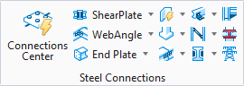
Accessed from: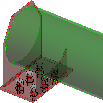
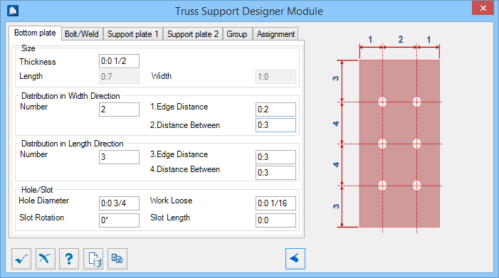
Bottom plate tab
Used to specify geometric values for the bottom plate in the connection.
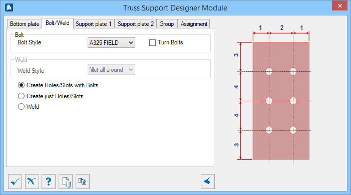
Bolt/Weld tab
Used to specify bolt and weld material data, as well as select the connection method used.
Support plate 1 tab
Used to specify geometric values for the end support plate.
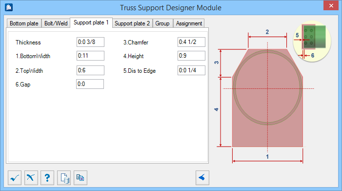
| Setting | Description |
|---|---|
| Thickness | Sets the thickness of the plate. |
| Bottom Width | Sets the total plate width where it is joined to the bottom plate. Denoted with 1 in the diagram. |
| Top Width | Sets the width at the top, between the chamfers. Denoted with 2 in the diagram. |
| Chamfer | Sets the height of the chamfer corner. Denoted with 3 in the diagram. |
| Height | Sets the height from the support plate to the chamfer. Denoted with 4 in the diagram. |
| Dis to Edge | Sets the distance from the edge of the bottom plate to the face of the support plate. Denoted with 5 in the diagram. |
| Gap | Sets a clearance gap from the support plate to the end of the truss member. Denoted with 6 in the diagram. |
Support plate 2 tab
Used to specify geometric values for the end support plate.
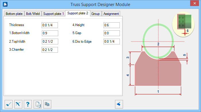
| Setting | Description |
|---|---|
| Thickness | Sets the thickness of the plate. |
| Bottom Width | Sets the total plate width where it is joined to the bottom plate. Denoted with 1 in the diagram. |
| Top Width | Sets the width at the top, between the chamfers. Denoted with 2 in the diagram. |
| Chamfer | Sets the height of the chamfer corner. Denoted with 3 in the diagram. |
| Height | Sets the height from the support plate to the chamfer. Denoted with 4 in the diagram. |
| Gap | Sets a clearance gap from the support plate top surface to the face of the truss member. Denoted with 5 in the diagram. |
| Dis to Edge | Sets the distance from the edge of the bottom plate to the face of the support plate. Denoted with 6 in the diagram. |
Group tab
Used to create a new OpenPlant Modeler group with the Substation Gallery objects.
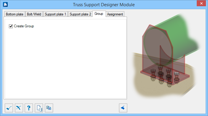
| Setting | Description |
|---|---|
| Create Group | Select this option to select additional shapes. Separate Substation Gallery objects are created. |
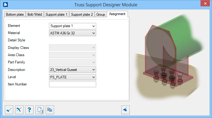
Assignment tab
Used to assign elements in the connection to a material, display class, area class, part family, level, etc.
Dialog Controls
| Setting | Description |
|---|---|
 OK OK
|
Closes the dialog and save your changes. |
 Cancel Cancel
|
Closes the dialog without saving changes. |
 Help Help
|
Opens online help. |
 Template Template
|
Saves and retrieve (Using Templates) settings to be used on other projects. |
 Clone Clone
|
Shifts focus to the geometry, allowing cloning the current structural object (stair, frame, truss, etc.) properties to match one or more objects selected in the view. |
  Show /Hide
Preview Show /Hide
Preview
|
Opens or closes, respectively, a flyout panel to display an illustration based on the tool. |