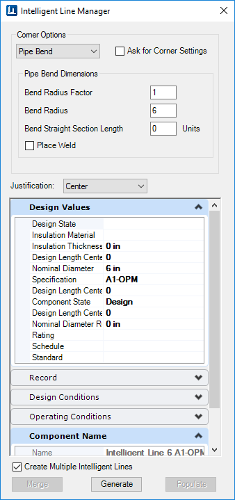
| Corner Options
|
When populating an intelligent centerline, bend and
branching components will automatically be placed either by:
- Using the default
values defined in the AutoBend and AutoTee tables
- Through the
AutoFittingRules.xml file.
Select either the Standard Elbow or Pipe Bend
option from the drop down list to determine how elbow/ bends are automatically
placed when routing a pipe run. Each option provides a different set of
additional fields to help define how the elbow or bend is selected and placed.
| Ask for Corner Type
|
When this is selected, the fields
underneath are disabled. When populating the centerline, you will be prompted
to select a bend option from the Spec Record Selection dialog whenever a corner
is encountered.
|
| Standard Elbows:
|
This option places an elbow when
routing a 90deg. angle in a pipe length. When selected, a set of Query Options
(shown above) are displayed to define how to select the correct elbow for
placement:
- Radius
Type: Select from either Long Radius, Short Radius or 3R.
- Place
Trimmed Elbow: When enabled, a trimmed elbow is placed.
- Stock
Angle: Used to define the angle of the trimmed elbow. Select one of the
available angles from the field.
|
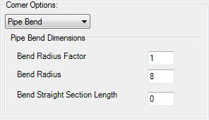
| Pipe Bends
|
The Pipe Bend option places a pipe bend
instead of an elbow where there is a bend with an angle which doesn't match any
of the elbows in the spec. When selected it display a set of fields used to
define the bend dimensions as shown:
|
|
| Justification
|
Defines the placement point for the components placed
on the centerline. The options available (Top, Center and Bottom) are relative
to the pi The options are relative to the piping component being placed:
- Top (Top of Pipe)
- Center (Center of
Pipe)
- Bottom (Bottom of
Pipe)
|
| Property Fields
|
The bottom section of the Intelligent Centerline
Manager displays a variety of property tabs that expand displaying editable
fields (in most cases) to define the property values for the center line.
A default component name is displayed in this field
concatenated from the active Pipeline defined in the Standard Preferences
dialog prefixed by the following string:
"Intelligent Centerline <Nominal Size> <Specification>"
The values for Nominal Size and Specification are
derived from the current values for those fields. They can be updated in the
Design Values section. The Component Name is automatically updated when the
values in any of these fields are changed.
The Line Number can be modified in the
Miscellaneous section of the dialog. Changes to the Line Number will
automatically be applied to the Component Name as well.
|
| Create Multiple Intelligent Lines
|
If you are working with a model with multiple line
segments which have EC Property values defined for them (either in the active
model, or a referenced DGN), this option will create multiple intelligent lines
from the segments, and copy the EC Property values for each segment to the new
intelligent line.
In order to process multiple intelligent lines, the
following properties must be the same:
LineNumber, Specification, Nominal Diameter,
Insulation Thickness, Insulation, State
If this option is not enabled, then one intelligent
line will be created from the multiple segments, using the EC Property values
from the last process line segment.
Note: In order to
be able to copy a line segment's EC Properties, you must first make some
changes to the OpenPlant schema files. Click the link below for the procedure
to modify the schema:
|
| Merge
|
The merge enables you to merge an intelligent line in
the model with a connecting SmartLine segment. When you click the Merge button,
then the unintelligent line segment will be merged with the intelligent line
and inherit its line properties.
The Merge button only enables when you have selected
both the intelligent line and the connecting SmartLine segment.
|
| Generate
|
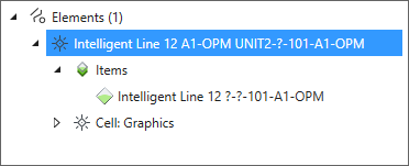
Creates the intelligent centerline from the selected
line segment(s). Once generated, the property values defined are assigned to
the line. The intelligent line is listed in the Properties dialog under the
line number it was assigned to as shown:
|
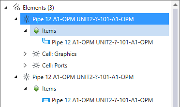
| Populate
|
When selected,
OpenPlant Modeler
begins the process of placing components on the intelligent
centerline using the AutoFitting method. When a branch or corner is
encountered, the AutoBend and AutoTee tables are used to select the correct
components to place according selections in the Corner Options section of the
IL Manager. Once the line has bene populated, Intelligent Line instances in the
Properties dialog (Shown Above) are replaced with the actual components that
have been associated with the line. (See Below)
|
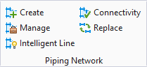
 Used to create intelligent
centerlines from line segments and smartlines, and populate those lines with
OpenPlant components. When using the Intelligent Line Manager, the active
pipeline settings are applied to the line segments/smartlines. A pipeline must
be defined before the Intelligent Line Manager can be used.
Used to create intelligent
centerlines from line segments and smartlines, and populate those lines with
OpenPlant components. When using the Intelligent Line Manager, the active
pipeline settings are applied to the line segments/smartlines. A pipeline must
be defined before the Intelligent Line Manager can be used.