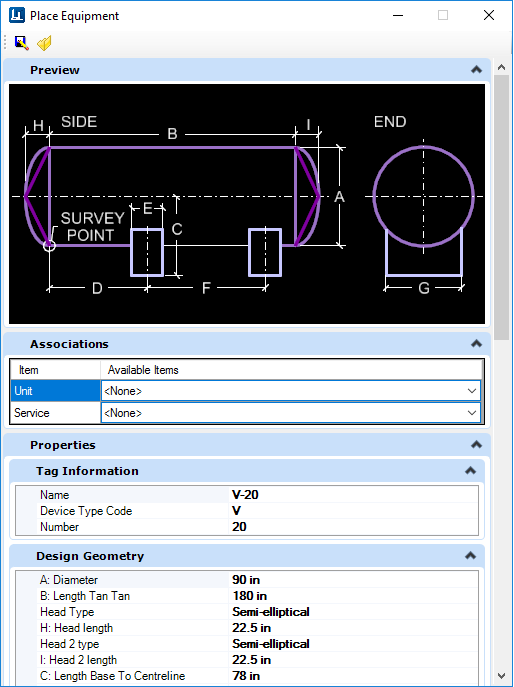
Place Equipment Dialog
Displays when placing a new equipment component allowing the user to define properties for the component.
Accessed when:- User selects an equipment component from one of the Equipment Galleries.
| Setting | Description |
|---|---|
Save

|
Saves the parametric properties defined in the Design Geometry group to a file. |
Load

|
Allows you to load saved parametric properties which were defined and saved to a file. These properties will populate the fields in the Design Geometry group. |
| Associations | This tab allows you to associate existing Unit and Service values to the equipment component. To create new values for Unit/Service, refer to the Standard Preferences. |
| Tag Information | Enter the tag number for the component here. |
| Design Geometry | Defines the parametric properties of the component. The property fields correspond with the dimensions displayed in the bitmap image at the top of the dialog. |
| General Info | Provides a list of editable fields which define the physical properties of the component being placed. |
| Design Conditions | Specific working conditions the component class was intended to operate in. |
| Record | Records information pertaining to the creation and modifications made to the area. These fields cannot be edited but are updated automatically when an equipment component is created or modified. |
| Operating Conditions | Represent real life conditions that a component will
most likely be exposed to.
When defining a pipe size for a pipe run, either enter a size directly into the field, or select a size from the drop down list. |
| Miscellaneous | Define various miscellaneous property values here. |
| Nozzles (PUMPS ONLY) | When placing pumps a Nozzles tab is added to define properties determining the size and placement location for the Suction and Discharge nozzles. |
Tag Browser (Available only when OPPID i-model is referenced)
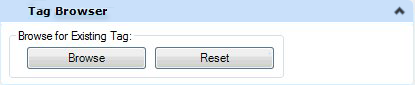
The Reset button will reset the tag number to its original value.
Detail Sketches
The Detail_Sketch property has been added to the OpenPlant3D schema at the DEVICE level, meaning you can define a detail sketch for a specific component to be included when generating an isometric using the OpenPlant Isometric Manager. This property can be defined when initially placing the component, or when modifying one. It is located in the Miscellaneous tabbed section as shown below:
Enter the name of the detail sketch cell into the field to include it when generating an isometric.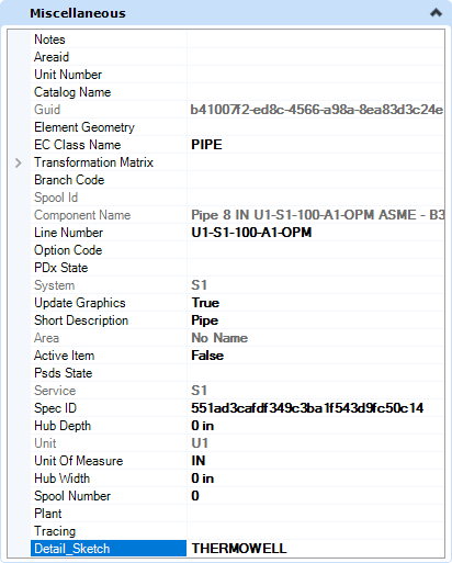
By default, the OpenPlant Isometrics Manager will look to the default cell libraries which are included with install, one of which is named Detail_Sketch.cel. The cell libraries are located in the Cell directory for each isometric style in the project. For example, the IFC style can be found in the following directory:
...\OPModeler_Imperial\DataSet\Isometrics\Styles\IFC\Cell\ If you define a detail sketch cell file in the Detail_Sketch property field, that cell must be included in one of the cell libraries or the isometric process will not find it causing an error. If you have existing detail sketches defined in a cell library, you can copy that file into the Cell directory for the isometric style and the Isometrics Manager will find it.Click Here for a detailed procedure on how to add a detail sketch to a cell library and include it on an isometric.