(Technology Preview) Named Presentations
When working with 3D models, some geometric components
need to display different symbols in different view contexts, and simple
projections may not be sufficient. The Named Presentations feature allows you
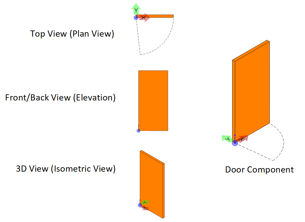
to do so. For example, consider a door component. You may want different
symbols of a door in different views as shown below.
Adding the elements you want to see in each view to the
corresponding Named Presentation will only show those elements when the door is
placed as a parametric cell in a design and the respective view orientation is
selected. For example, Top view will only show the door in plan and its swing
when these elements are added to the 'Top' named presentation.
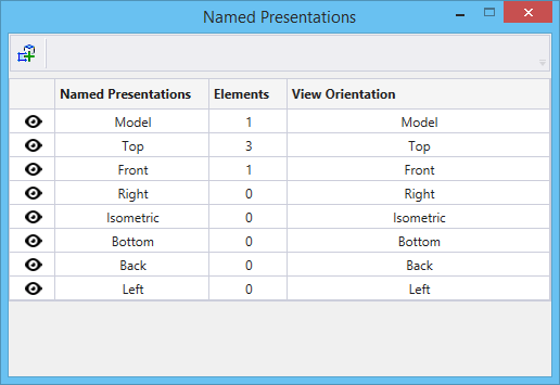
Named Presentations Dialog
 Used to manage named
presentations.
Used to manage named
presentations.

Named Presentation View Attribute
In the View Attributes dialog's Presentation section, a new icon called Named Presentation is added. If on, named presentations are applied to the selected view.
Elements in a design that are not added to any Named presentation will display in all Views. To prevent an element from displaying in any of the standard views you must add it to the Model named presentation. Elements added to the Model named presentation will only display in non-standard views like Isometric view or Rotate view.
Workflow for Using Named Presentations
Following is the general workflow for using named
presentations:
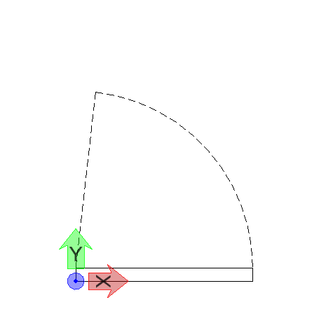
- In a model, draw the desired 3D model. For example, a door.
- In a different view orientation, place elements that you want to view for the model in that view orientation. For example, for a door model, in the Top view, you will draw the commonly used symbol of door in plan views, which is a rectangle with an arc and line indicating the door and its swing.
- Open the Named
Presentations dialog.
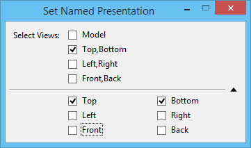
- Select the
Set to Named Presentation tool and in its tool
settings window, select the desired views to which you want to add the
elements.

- Select the desired
elements and enter a data point. In our example, select the door symbol in Top
view.
The elements are added to the selected named presentation.
- Now place the model as a parametric cell in another DGN.
- In the View Attributes
dialog in the DGN where you have placed the parametric cell, make sure the
Named Presentation view attribute is turned
on.
- Change the orientation to the one that has named presentation created and observe that the elements that you included for that named presentation are displayed instead of the original cell. So, in our door example, in the Top view, you will see just the door symbol, which is a rectangle with an arc and line.