IsoSheet Manager
The IsoSheet Manager allows you to generate Iso Sheets from the selected pipelines in the Pipeline Manager. The Iso Sheets can then be generated using the Bentley OpenPlant Iso Manager application.
Accessed from the Pipeline Manager The IsoSheet Manager is made up of two sections: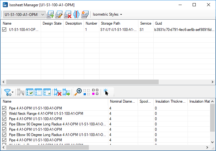
IsoSheet Grid
The IsoSheet grid displays at the top of the IsoSheet Manager and lists the isosheets currently defined for the selected pipeline. The grid has a toolbar at the top which provides the following options to Add, Edit or Delete isosheets.
- ...\Configuration\Workspaces\WorkSpace\WorkSets\OpenPlantImperial\Standards\Modeler\Modeler.cfg
- ...\Configuration\Workspaces\WorkSpace\WorkSets\OpenPlantMetric\Standards\Modeler\Modeler.cfg
- ...\Configuration\Workspaces\WorkSpace\WorkSets\OpenPlantMixedMetric\Standards\Modeler\Modeler.cfg
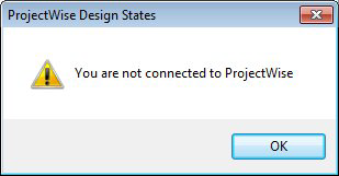
PROJECTWISE_ISOMETRIC_WORKFLOW_NAME =If a workflow is not defined, you will get the following error message when trying to set a Design State from any interface where it can be defined (such as IsoSheet Manager, Create Pipeline dialog, etc.) Once you have defined an isometric workflow name in the %project%.cfg file, a list of design states will display as a drop down list in the Design State field in any of the dialogs where the Design State can be defined.
| Pipeline List | The drop down list at the top left of the
Isosheet Manager lists the available pipelines to be selected. When a pipeline
is selected, its components are displayed in the Components Grid. From there
they can be selected for an isosheet.
The list is generated from the pipelines which were selected in the Pipeline Manager when the Isosheet Manager was launched. If no pipelines were selected from the Pipeline Manager then all of the available pipelines are listed.
|
Create a new Iso Sheet

|
Creates a new iso sheet from the components
enabled in the components grid. Components can be selected in the following
ways:
Create Single IsoSheet from Multiple Pipelines If multiple pipelines were loaded into the IsoManager you are able to create a Single IsoSheet from the components of the multiple pipelines. To do this, you must pick the Select All option from the Pipeline List icon defined above. |
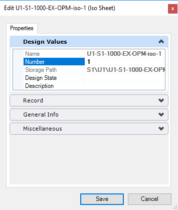
Edit Iso Sheet

|
Displays the properties dialog shown below for
the iso sheet allowing you to edit the certain properties.
Note: For an iso
sheet to be run through the Iso Manager, you must have a Design State defined
in the properties dialog.
How To
|
Delete Iso Sheet

|
Deletes the selected iso sheet. |
Manage Joint Associations

|
This icon displays the Joint Associations Manager dialog, which list the joint information placed between connecting pipelines in the model. This allows you to view the joint details, including the fasteners and seals, move the joint association from one pipeline to the connecting pipeline if desired. |
Generate Iso(s)

|
This option (which is also
available from the Pipeline Manager) generates isometrics from the selected
isosheet(s) and will open the OpenPlant Isometrics Manager providing options to
the user to view the isometric sheets as well as the log files created with the
isometrics.
When running this option from the Isosheet Manager, you have the option to select which isosheets to generate isometrics from. When run from the Pipeline Manager, isometrics are automatically generated for all isosheets for the selected pipeline. How To |
| Isometric Styles | Press the arrow button to select an isometric style from the list: |
IsoSheet Components Grid
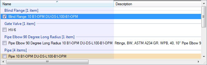
The components grid lists the components that are associated with the selected pipeline. A toolbar with the following options is available for the components grid:
| Component Sorting Filters | A drop down list provides the following
options to filter what and how the components for the selected pipeline are
displayed in the components grid:
|
| Component Selection | The following options are available for
quick multi-component selection:
|
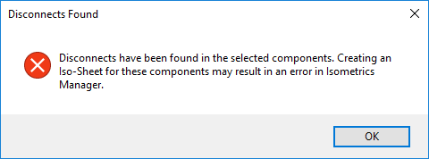
Remove component(s) from Isosheet

|
Lets you remove components from the associated isosheet as long as the removal does not cause any disconnect. |
Move unassigned component(s) to Iso Sheet

|
Will move selected unassigned components to
an iso sheet. You will be prompted with a
common line selection dialog listing the available iso
sheets.
Note: Select the
Show components not assigned to any isosheet sorting option to identify which
components are unassigned.
How To
|
| View Options | The following options are available: |
Select Component

|
Check off components in the list and click this button to select the components in the model for editing mode similar to if you had used the standard |
 : Displays all of the components
for the selected pipeline.
: Displays all of the components
for the selected pipeline.
 : Displays all of the components
for the isosheet selected in the Isosheets grid.
: Displays all of the components
for the isosheet selected in the Isosheets grid.
 :
:
 : This option only displays the
components for the selected pipeline which have yet to be assigned to an
isosheet.
: This option only displays the
components for the selected pipeline which have yet to be assigned to an
isosheet.
 : This button only enables when a
component is already selected. It will select all of the components that are
connected to the selected. component.
: This button only enables when a
component is already selected. It will select all of the components that are
connected to the selected. component.
 : Enables the checkbox next to all
of the components in the list.
: Enables the checkbox next to all
of the components in the list.
 : Disables the checkbox for all
components in the list.
: Disables the checkbox for all
components in the list.
 : Will invert whatever the current
selection is. (For Example: If currently all but six components are selected,
this option will enable the six not currently selected, and disable the
remaining components)
: Will invert whatever the current
selection is. (For Example: If currently all but six components are selected,
this option will enable the six not currently selected, and disable the
remaining components)
 : Zooms into the selected
component.
: Zooms into the selected
component.
 : Hides all other components in
the model except for the selected component.
: Hides all other components in
the model except for the selected component.
 : Highlights the selected
component in the model.
: Highlights the selected
component in the model.
Right-click on any of the column headers in either the Isosheets or Component grids and a popup menu displays providing the following options to modify/sort the information displayed in the grid columns: