Updates to Victaulic Catalog
A Typical Victaulic Groove Joint between piping components has both Male Groove Ends and then Connected using a Victaulic coupling
However, there can be cases where both ends are not grooved e.g. an adapter nipple with one end as grooved and other end is threaded.
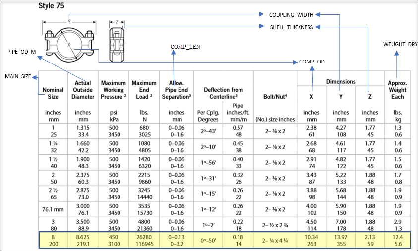
A typical Victaulic Cam and Groove Coupling is drawn in OpenPlant Modeler according to following mapping of the properties in Catalog\Spec mdb file
List of Groove Profiles Supported in OpenPlant Modeler CONNECT Update 9
Apart from Standard\Original Cam and Groove System, following Groove profiles are now supported in OpenPlant Modeler . Their related components and Joints are now available in OpenPlant Modeler Catalogs and Schemas.

Victaulic Hole Cut System
New Variables added and Graphics\Placement updates
- OPM_MATCH_PROPERTY_MAP_MATERIAL - Added a New Variable OPM_MATCH_PROPERTY_MAP_MATERIAL to support different Material Combinations incase Material is added as a Matching criterion. Most of the Victaulic couplings are of Ductile Iron Material whereas Piping components material can vary. So, in order to allow placement of different Material Victaulic coupling on piping components this variable can be used.
- OPM_AUTOFITTING_SELECTION_GRID_FOR_ELBOW - Added a new variable OPM_AUTOFITTING_SELECTION_GRID_FOR_ELBOW. Set its value to 1 to see the selection grid dialog for pipe elbow when placed through autofitting. By default, Washer\gasket is not part of Flange Groove Joint, its optional and user can add it if needed.


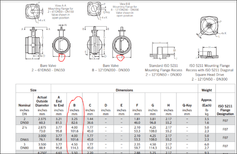
- Victaulic Butterfly and Gate Valves Graphics - For Non-Flanged Victaulic Butterfly and Knife Gate Valves, we are using FLNG_OD_M column in catalog\spec mdb file as total valve width and its value will be mapped from Outer Shell diameter of valve (B property in below snap). This is done to draw valve graphics close to actual valve graphics.
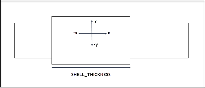
- Aquamine Coupling Graphics - Aquamine Couplings are different from rest of Victaulic Coupling as they do not have Nuts and Bolts. So their graphics are created as follows: When looking from the front view, the placement point can be marked as below. The shellThickness is thickness of the coupler as marked in image.
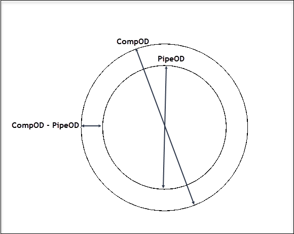
- From the right view, the placement points are mainly y axis and z axis. The width of the coupler is calculated by subtracting Pipe outside diameter (PipeOD) from Component outside diameter (CompOD). PipeOD value is taken as Component inside diameter.
- CompOD and PipeOD must not be same to draw coupler in right shape.