Consistency Manager
This option lets you view the database consistency between what components are placed in the 2D model vs the 3D model. It also provides options to generate and view reports of the database records stored on PlantSight.
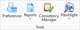
This is a common tool accessed from the Tools group which is available from the Piping, Equipment and Raceway ribbons.
Once the update has been performed, the following dialog displays. By default, the Home tab is displayed which is where you can run a query and view the results of the components in the imodel.
The Settings tab contains settings which control what information is displayed and how it is formatted under the Home tab.
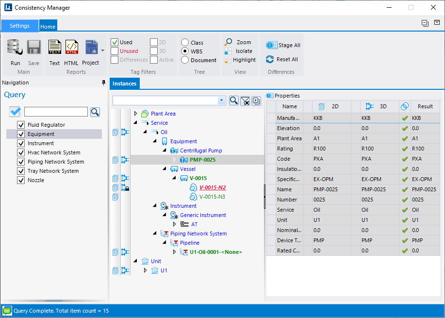
Home Tab
| Setting | Description | |
|---|---|---|
| Run Query | This option runs the BIM query based on the criteria selected in the Navigation tree. When the query has been run, the results are displayed in the Instances tree. | |
| Save | The Save button enables when changes are made in the Consistency Manager. Click to Save the changes. | |
| Reports | The Consistency Manager has a list of reports that
can be run and viewed. By default the Text and HTML reports are available. The
XML and JSON reports can be added from the
Settings tab under the Reports section.
When the report is run it is opened in a view
window using the format selected.
|
|
| Project Reports | Allows for project wide reporting when working with
a PlantSight integrated WorkSet. A set of default reports are included with the
install but additional reports can be added through the Report Designer
available from the
OpenPlant Project Administrator.
The display of the Project reports list can be toggled on/off in the Settings tab under the Reports section. Note: If working
locally and not connected to a PlantSight integrated WorkSet you can still run
project wide reports which include an referenced drawings. A setting is
included in the report
Options dialog which lets you include referenced drawings
when querying data for a report.
|
|
| Tree Query Filters | Ths options in this section control how the query
results are displayed. Two different sets of display options are available:
|
|
| Tree Display Options | The hierarchy options determine how the results are
displayed:
For newly added classes, the MappingsTagClass.json file must
be modified to display them in the Consistency Manager. This file is found in
the following location (using the default OpenPlantMetric Workset as an
example):
Note: ...\ProgramData\Bentley\OpenPlant CONNECT Edition\Configuration\Workspaces\WorkSpace\WorkSets\OpenPlantMetric\Standards\OpenPlant\Mapping\MappingsTagClass.json |
|
| View Options | Provides options to view the selected item in the Instances tree: | |
| Differences | The Consistency Manager allows for global selection of Instances with property differences between the 2D and 3D drawings. Any resolved property items (checked checkbox in property grid) will be saved. | Reset All: |
Navigation Tree
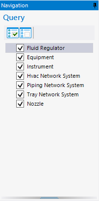
 Search: Enter the search criteria
into the field and click this icon to filter the display.
Search: Enter the search criteria
into the field and click this icon to filter the display.
 Clear: Click to clear the filter
and refresh the tree.
Clear: Click to clear the filter
and refresh the tree.
 Expand/Collapse: Expands or
collapses the current tree view.
Expand/Collapse: Expands or
collapses the current tree view.
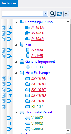
Instances/Properties
| Setting | Description |
|---|---|
| Search Options | The following search options are available to filter the results display: |
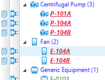
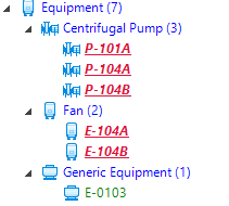
| Column Indicators | The Instances section contains two columns to the
left with icons that indicate whether items are placed in a 2D document, 3D
model or both:
Note: For a full
description of all of the symbols used in the Consistency Manager, click
Settings tab and view the Legends section.
|
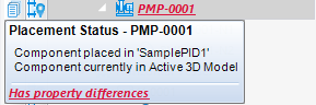
| Color Coded Results | The color of the text for the instances have a purpose in defining the placement status of the instance. |
 Collapse: Click to collapse all
nodes in the Instances tree.
Collapse: Click to collapse all
nodes in the Instances tree.


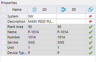
 icon in the last column if the
property values are the same in the 2D document and 3D model. If the values are
different then the
icon in the last column if the
property values are the same in the 2D document and 3D model. If the values are
different then the
 icon is displayed.
Context Menu
| Setting | Description |
|---|---|
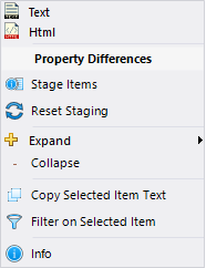
| Report Types | By default there are two types of report formats
which can be run from the menu.
Additional report formats can be added by enabling them under the Reports settings in the Settings tab. |
| Property Differences | Select whether to Stage Items or Reset Staging to apply to the Instances Tree. These options operate the same as the ribbon options detailed above. |
| Expand/Collapse | Expands or collapses the current tree view. |
| Copy Selected Item Text | Copies the currently selected tree node to the clipboard |
| Filtered on Selected Item | Filter display of the Instances tree based on the currently selected node. |
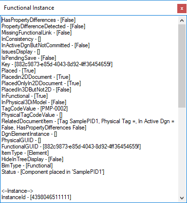
| Info | Displays a popup with property info for the selected node. |
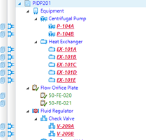
| Create Custom Component | When you click on a component tag which has not been
placed in the 3D drawing, you will have the opportunity to use the tag to
create a new Custom Component from native elements in the drawing.
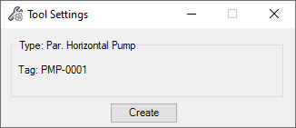
This option behaves the same as the
Create Equipment option available from the Equipment
toolbar. The only difference is when the Tool Settings dialog displays, you are
not prompted to select a component class as it is already determined. Once you
have selected the element(s) to create the equipment from the following dialog
displays:
When you click Create, the new component is created inheriting the properties from the selected tag. These can be modified using the Properties dialog. |
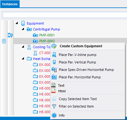
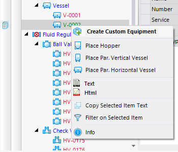
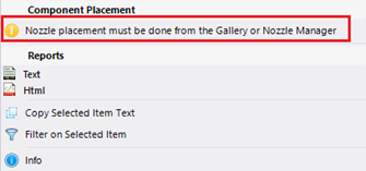
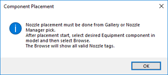
| Placement Options | When you click on a component instance which has
been placed in a PID and not placed in the 3D model placement options will
display for the component. The placement options are related to the class of
component instance selected.
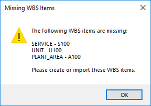
Once you select a placement option continue with the normal placement procedure for the component. The Properties dialog will display so you can define any properties for the property before placing in the model. If the WBS items defined for the component in the
PID drawing have not been defined in the 3D model, the following message
displays:
Click OK then define the WBS items using the Standard Preferences dialog. |