Isometric Style Configuration - Coordinates
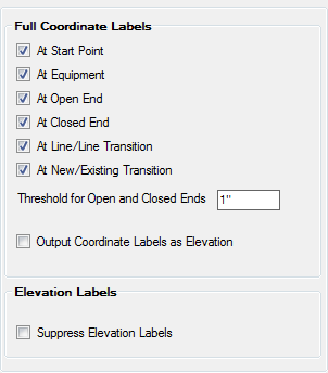
The options in the Coordinates section let you specify where to place coordinate labels and/or use Elevation Labels instead of full coordinate labels. Once the settings have been defined, slick the Save button to apply them.
| Setting | Description |
|---|---|
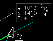
| At Start Point |
Each isometric has a start point and this point can be labeled. The purpose of this option is to be able to have exactly one coordinate label in the isometric when all the other options are unchecked. The coordinate label will display similar to the image below: |
| At Equipment |
Outputs a coordinate label at the transition from NEW to equipment. |
| At Open End |
Outputs a coordinate label at an open end. An open end is basically an unconnected node which the software interprets as open. |
| At Closed End |
Outputs a coordinate label at a closed end. A closed end is basically an unconnected node which the software interprets as closed. |
| At Line/Line Transition |
Outputs a coordinate label where a line transition occurs. The way this option operates is when OpenPlant Isometrics Manager sees a transition from NEW to CONTINUATION and none of the involved components include a nozzle, this option is used. |
| At New/Existing Transition | Outputs a coordinate label where a transition from NEW to EXISTING occurs. |
| Threshold for Open and Closed Ends |
This is specific for OPEN/CLOSED ends. When the diameter of the open/closed end is smaller than the threshold value the coordinate label will be suppressed. |
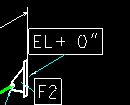
| Output Coordinate Labels as Elevation |
All the previous option output a full coordinate label. This option only outputs the elevation as shown below: |
| Suppress Elevation Labels |
The full coordinate labels as set by the above options always output on ports. It may however be required that in selected intersection points (Tee, elbows, olets) an elevation coordinate is required. Typically OpenPlant Isometrics Manager outputs only the minimal required set. |