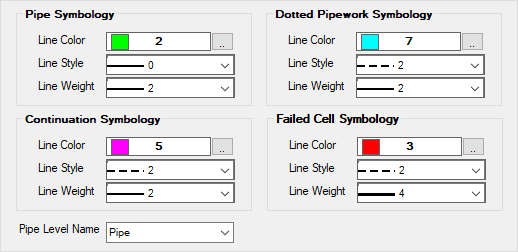
Isometric Style Configuration - Component Placement
The configurations
in this option are shown below.
| Setting | Description |
|---|---|
| Pipe Symbology | This Symbology defines settings for line used to
draw pipe.
|
| Continuation Symbology | These settings are for elements that are not really
part of the current iso sheet but are included just to give an idea of the
continuing pipe work on another sheet.
These element are not annotated and do not show up in the BOM. (See the field descriptions for Pipe Symbology above.) |
| Dotted Pipework Symbology | The options under this section define "Existing"
components. The components are existing and "New" components are usually
connected to them. (For instance, existing components may be used when an
existing plant is re-vamped.)
These elements are normally not annotated except for the tie-in point and never show up in the BOM. (See the field descriptions for Pipe Symbology above.) |
| Failed Cell Symbology | If cell does not found in cell library, it is
denoted in isometric drawing using settings in Failed Cell Symbology.
(See the field descriptions for Pipe Symbology above.) |
| Pipe Level Name | Select level from the list to define Pipe Level. |
When finished making any changes in the fields, click Save to apply the changes.