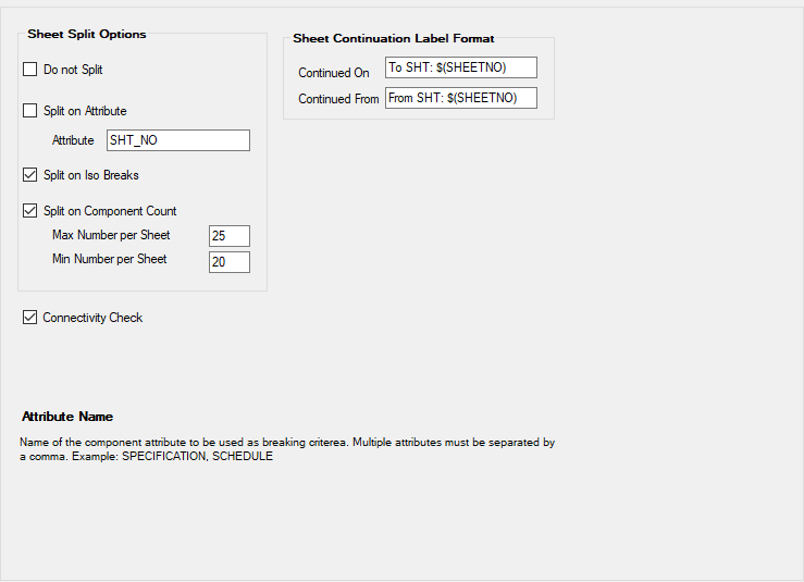
| Do Not Split
|
When this option is selected the input will not be
split. The name of the resulting isometric will match the name of the input.
|
| Split on Attribute
|
When this option is selected the isometric will be
split based on a component attribute. Splitting occurs in a joint where the
connected components have different values for the specified attribute. The
following conditions control how this split method operates:
- The value for the
split attribute is assumed to be a number. Only values greater than zero are
seen as valid.
- This method is not
used when none of the components in the isometric has a valid value for the
split attribute.
This method will not successfully process Isos when:
- There are some (not
all) components without a valid value for the split attribute.
- The input contains
disconnects and the Connectivity Check option is enabled.
- If the distribution
of the split attribute is not logical. For example: The same value is used for
more than one set of interconnected components.
|
| Split on Iso Breaks
|
When checked this split option is used when all the
previous methods cannot be used or have not been checked. The input file must
contain at least one isometric break point defined in the model. The input will
then split on the isometric break points indicated in the piping design system.
The method will only fail if the input file contains
disconnects and the Connectivity Check option is enabled.
|
| Split on Component Count
|
When checked this option is used when all of the
previous methods cannot be used or have not been checked. The result isometrics
will contain a maximum number of component as specified by the user. The
minimum number of components per sheet will vary. The margin between minimum
and maximum number of component is used to find a natural split location like a
field joint.
The method will only fail in case the input
contains discontinuities and the connectivity check is enabled.
|
| Connectivity Check
|
When checked the input will be checked for
discontinuities. When discontinuities are found the isometric will always be
marked as failed. The isometrics however will be produced and can assist the
user in locating the discontinuities in the model.
Note: Currently it
is impossible to produce an intermediate file with discontinuities. The OPIM
shell stops processing in case discontinuities are found and produces an error
message that doesn't assist the user in any way. Future OPIM versions should
disable the continuity check.
|
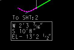
| Continued On
|
Contains an expression for the sheet to sheet
reference. The expression can use drawing attributes related to the neighbor
sheet. This expression is used for a reference label for a lower to a higher
sheet number.
|
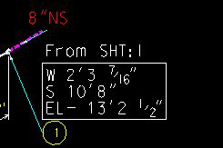
| Continued From
|
Contains an expression for the sheet to sheet
reference. The expression can use drawing attributes related to the neighbor
sheet. This expression is used for a reference label for a higher to a lower
sheet number. The expression can be the same as the Continued On expression.
|