Isometric Style Configuration - Leader
The configurations in this option (shown below) define the settings for Leader.
The descriptions in the table below will apply to both the Insulation and Tracing options:
When finished making any changes in the fields, click Save to apply the changes.
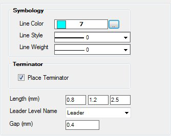
| Setting | Description |
|---|---|
| Line Color | Define color of the leader line. Click on browse button to open Color Table and select any color from the color table. |
| Line Style | Select line style from the list for the leader line. |
| Line Weight | Select line weight from the list for the leader line. |
| Place Terminator | Determines whether to place terminators in the isometric drawing as shown below: |
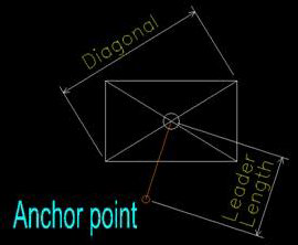
| Length (mm) | The values are multiplication factors and determine the distance of the label center relative to the anchor point For example: Suppose you have a label as shown below, a simple rectangle. The leader line is supposed to go from the anchor point to the center of the label. The length of this leader line equals the diagonal of the label multiplied by one of the length fields. Many label positions are evaluated at different distances and a suitable position with as few overlaps as possible is chosen. |
| Leader Level Name | Select level from the list to define Level for Leader lines. |
| Gap (mm) | Define gap between origin point of component and start of leader line. |