Schematic
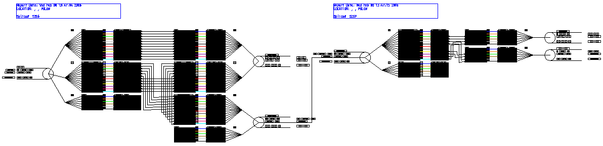
This command generates a schematic fiber path throughout the entire network to all terminations of fibers from a given start point.
Generate a Fiber Schematic
- From the OpenComms Fiber Tab, select the Schematic icon from the Splicing Reports section.
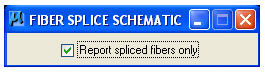
- The Fiber Splice Schematic dialog box opens.
- Activate the Report spliced fibers only check box to limit the report to spliced fibers.
- Select a Splice on the design file. Identify the span to display on the left side of the report and press Accept to generate the report.
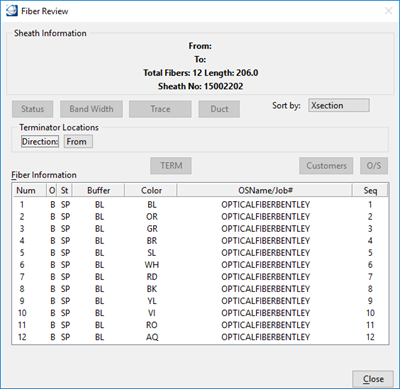
- A Fiber Review dialog box opens.
- Highlight a fiber in the Fiber Information list.
- Click Term to display the
termination device.
Note: The splice schematic drawing that is generated will, by default, display all buffers and fibers from the input side of the splice to any number of outputs present. The Compress option, if used, will compress the display of fibers to only display buffers if the fibers within those buffers are connected from sheath to sheath in a 1 to 1 manner.
- Click Process to create the schematic drawing. You must enter a name in order for the processing to occur.