Equipment
Once the racks, ports and slots are defined, the Equipment to be installed in the racks must be defined.
Open the Equipment Dialog Box
- From the File > OpenComms Settings > ISP dialog select the Equipment tab.
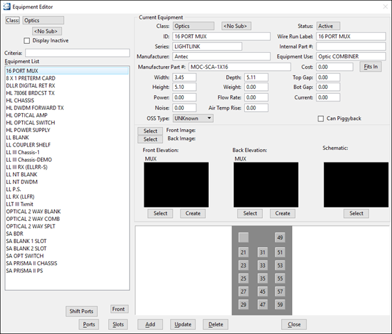
- The Equipment Editor dialog box opens.
Edit an Existing Equipment Model
- Select an equipment device from the Equipment List. Highlighting the equipment loads the information into the dialog box.
- Edit the Equipment Editor input fields as necessary.
- Click Update to save changes into the spec file.
Add an Equipment Model
- Key in the equipment ID in the database field.
- Click Add to save the equipment into the spec file and to make the dimension fields available.
- From the Class pull-down menu, select a class and a sub class.
- From the Status pull-down menu, select active or inactive. An inactive equipment stops being available when placing equipment.
- Key in Wire Run Label, Series name, Manufacturer name, Manufacture Part #, Internal Part #, Equipment Use and Cost.
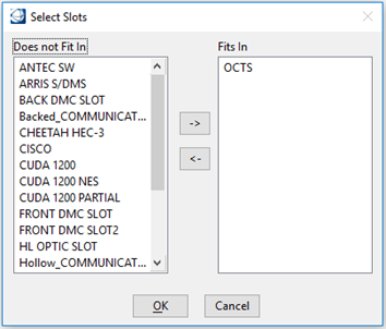
- Click Fits In to designate a piece of equipment (card) to fit in a particular slot.
- Enter the equipment Width, Height, Depth, Top and Bottom Gap.
- Enter the equipment Power, Flow Rate, Current, Noise and Air Temp Rise.
- The OSS Type pull-down menu is only used when the Inside Plant will be exported to a status-monitoring database. Bentley Systems customize this for each customer's requirements. Contact your sales representative for more information.
- Select the Can Piggyback check box to define if this equipment cannot be placed in a rack; but rather that it can be attached to another piece of equipment, like a two-way splitter attached to a patch panel port.
- From the Front and Back Image pull-down menu, select an image to associate to the front and back of the equipment that is used during the rack elevation creation.
- Select the cells to use for the front and back elevation and for the schematic files.
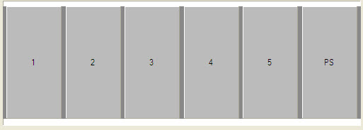
- The shaded area at the bottom of the dialog box is a representation of the device and displays ports and slots as defined.
- Click the Front/Back button to setup and check for the correct ports and slots placement.
- Click Shift Ports to move ports on the equipment.
- Click Ports to add/edit ports on the equipment.
- Click Slots to add a slots to the equipment.
- Click Update to save the equipment into the spec file.
Delete an Equipment Model
Edit an Existing Port on an Equipment Model
- From the Equipment Editor dialog box, highlight an equipment and select Front or Back.
- Click Ports.
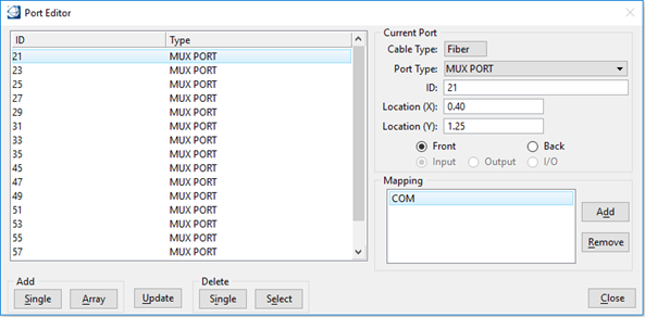
- The Port Editor dialog box
opens.
The Port Editor dialog box defines the Port type and location(s) of each Port on a device. The Port locations can be defined individually or using an array.
- Select a port from the Port List. Highlighting the port loads the information into the dialog box.
- Edit the Port Editor input fields as necessary.
- Click Update to save changes into the spec file.
Add a Single Port to an Equipment Model
- From the Equipment Editor dialog box, highlight an equipment and select Front or Back.
- Click Ports.
- The Port Editor dialog box opens.
- Select a Cable Type and Port Type.
- Enter a port ID.
- Define the location (x,y) of the port. The x location starts from the upper left corner of the device (front & back) and is defined, in inches, from left to right. The y location starts from the upper-left corner of the device and is defined, in inches, from top to bottom. For example: 0,0 would be the upper-left corner, while 4,2 would be four inches to the right of the left corner and two inches down.
- Select the port location on the Front or on the Back of the device.
- Select the type of port: Input, Output or I/O (Thru) Port.
- From the Mapping section, click Add.
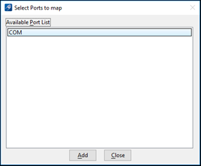
- The Select Ports to Map dialog box opens.
- Select a port from the Available Port List and click Add to create a connection between the two ports.
- Click Add Single to save the port settings. Adding a Port using the Single button is very time consuming when adding more than a couple of Ports. An Array button is used to create a group of Ports.
Add an Array of Ports to an Equipment
- From the Port Editor dialog box, select a Cable Type, a Port Type and enter a numeric value for the port ID.
- Click Add Array.
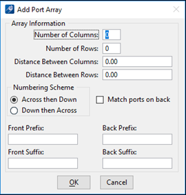
- The Add Port Array dialog box opens.
- Enter the number of columns and rows being defined.
- Enter the distance, in inches, between columns (Y).
- Enter the distance, in inches, between rows (X).
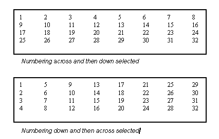
- Select the ports numbering scheme: Across the panel by rows in the X direction or Down the panel by columns in the Y direction. For example:
- Select Match Ports on Back to automatically create ports on the back while mapping the front and back ports. Mapping is accomplished when a port on the front is identified to map/match to a port on the back. Such as: Port 1 mapped to Port 1b.
- Key in Front and Back Prefix and Suffix to add to the number.
- Click OK to initiate adding the defined Port Array.
Delete a Single Port
- From the Port Editor dialog box, select a port from the port list.
- Click Delete Single.
- The port is deleted from the spec file.
Delete a Group of Ports
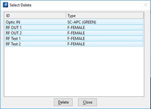
- From the Port Editor dialog box, click Delete Select.
- The Select Delete dialog box opens.
- Select multiple ports by holding the shift key.
- Click Delete to delete the selected ports.
- The ports are deleted from the spec file.
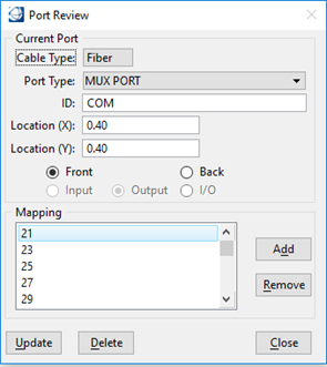
Review a Port
- From the shaded area at the bottom of the dialog box, click on one of the ports.
- The Port Review dialog box opens.
- Edit the Port Review input fields as necessary.
- Click Update to save changes into the spec file.
Edit a Slot on an Existing Equipment Model
- From the Equipment Editor dialog box, highlight an equipment and select Front or Back.
- Click Slots.
- The Slot Editor dialog box
opens.
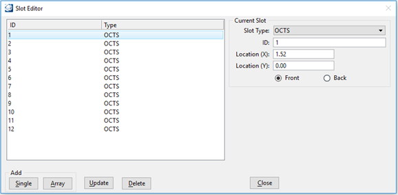
The Slot Editor dialog box defines the Slot type and location(s) of each Slot on a device. The Slot locations can be defined individually or using an array.
- Select a slot from the Slot List. Highlighting the slot loads the information into the dialog box.
- Edit the Slot Editor input fields as necessary.
- Click Update to save changes into the spec file.

Add a Single Slot to an Equipment Model
- From the Equipment Editor dialog box, highlight an equipment and select Front or Back.
- Click Slots.
- The Slot Editor dialog box opens.
- Select a Slot Type and enter an ID.
- Define the location (x,y) of the Slot. The x location starts from the upper left corner of the device and is defined, in inches, from left to right. The y location starts from the upper-left corner of the device and is defined, in inches, from top to bottom. For example: 0,0 would be the upper-left corner, while 1,4.5 would be one inch to the right of the left corner and four and a half inches down.
- Click Add Single to save the slot settings.
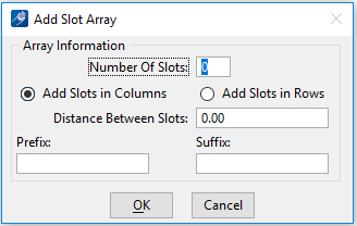
Add an Array of Slots to an Equipment Model
- From the Slot Editor dialog box, click Add Array.
- The Add Slot Array dialog box opens.
- Enter the number of slots being defined.
- Choose between adding slots in columns or in rows.
- Enter the distance, in inches, between slots.
- Key in Prefix and Suffix to add to the number.
- Click OK to initiate adding the defined Slot Array.
Delete a Slot on an Equipment Model
- From the Port Editor dialog box, select a slot from the slot list.
- Click Delete.
- The slot is deleted from the spec file.
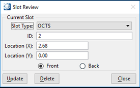
Review a Slot on an Equipment Model
- From the shaded area at the bottom of the dialog box, click on one of the slots.
- The Slot Review dialog box opens.
- Edit the Slot Review input fields as necessary.
- Click Update to save changes into the spec file.
To Associate a Card to a Slot on an Equipment Model