Signal Levels Calculation
The Calculations command offers the ability to calculate receiver input signal levels on selected nodes.
Calculation of a Single Node
- From the Engineering Calcs dialog box, click Single calculations.
- Select the node on the map receiving light.
- Select the device on the map containing the laser.
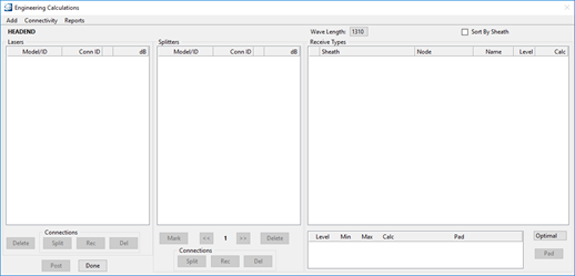
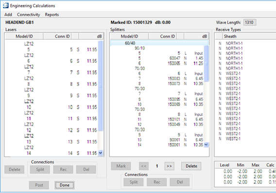
- The Engineering Calculations
dialog box opens.
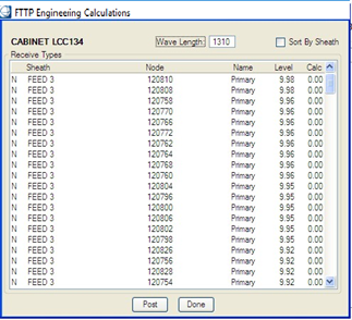
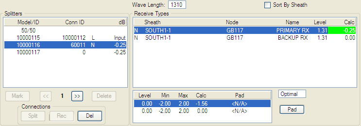
The dialog box is divided in three major sections: a laser section, a splitter section and a receive types section. This last section is automatically filled in with the node internal modules.
- From the Wave Length pull-down menu, select a wave length.
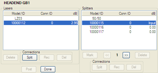
- Select Add > Laser to add a laser to the Lasers section.
- Select Add > Splitter to add a splitter to the Splitters section.
- Select the laser from the Lasers section and the splitter input from the Splitters section that you want to connect.
- Click Split to connect the laser output and splitter input together.
- A database connection ID is applied to the laser output and splitter input. The output levels of the splitter are also updated.
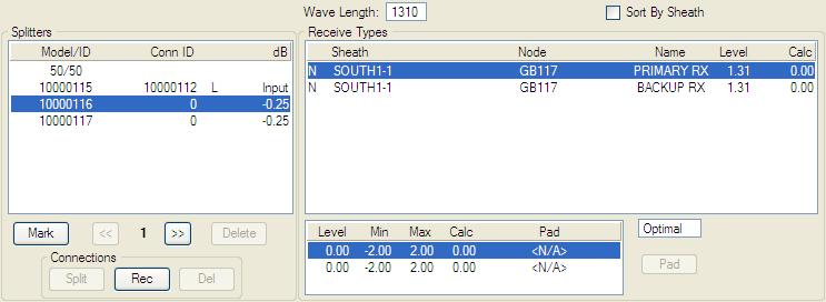
- Select one output from the Splitters section and one receiver from the Receive Types section that you want to connect.
- Click Rec to connect the splitter output and receiver input together.
- A connection ID is applied to the splitter output. The input level of the receiver is also updated.
- From the Receive Levels section, select minimum, optimal, or maximum from the pull-down menu and click on Pad to automatically insert a pad on the connection. Click UnPad to remove the highlighted pad.
- Highlight one of the Conn ID and click Del from the Connections sections to delete the laser or splitter link.
- Highlight one of the Lasers or Splitters section and click Delete to delete the laser or splitter link.
- Click Post to save modifications to the database.

Optimize Laser/Splitter Selection
- From the Engineering Calcs dialog box, click Global calculations.
- Select the device on the map containing the laser.
- The Engineering Calculations dialog box opens.
- From the Wave Length pull-down menu, select a wave length.
- Select Connectivity > Optimize.
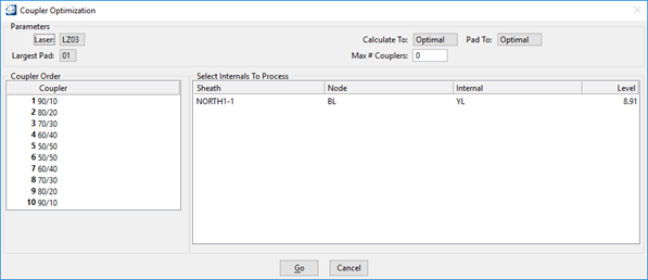
- The Coupler Optimization dialog box opens.
- Highlight the receivers to optimize.
- Select the laser to use with the selected receivers.
- Choose to what level setting (minimum, optimal, or maximum) the input signal level and the pad selection will be calculated.
- Choose the largest pad value to use and the maximum number of coupler to use during the optimization process.
- Click Go to proceed with the optimization.
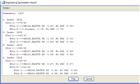
- The Engineering Optimization Report opens.
- Select Output > Text File to save the report into text file format.
- Click Post to apply the configuration.

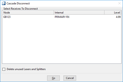
Disconnect Connectivity from a Laser to Receiver
- From the Engineering Calculations dialog box, select Connectivity > Disconnect.
- The Cascade Disconnect dialog box opens.
- Select the Receiver to disconnect and click Go.
- The receiver disconnects. Activating the Delete unused Lasers and Splitters check box removes unused splitters and lasers from the engineering calculations.
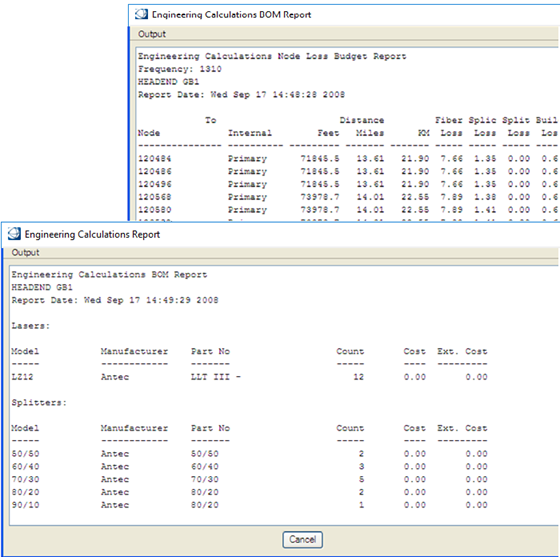
Creating a Laser, Node, or BOM Report
- From the Engineering Calculations dialog box, select Report > [laser, node, or BOM].
- The selected report dialog box opens.
- Select Output > Text File to save the report into text file format.
- Click Cancel to close the dialog box.
Calculating an FTTx Network