Inside to Inside
Connect Equipment Together with Jumpers
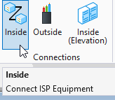
- From the Connections section of the ISP Tab click the Inside command:
- Select a rack on the floor plan containing the first equipment to connect.
- Select a rack on the floor plan containing the second equipment to connect.
- The Inside Plant - Connections dialog box opens.
- Select equipment from each rack and press the Connect button to connect ports on the selected equipment.
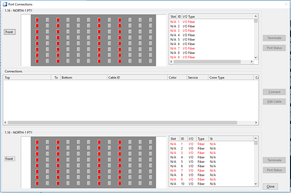
- The Port Connections dialog box opens.
- Click the Front / Back button to view the front or back of the equipment, respectively.
- Select the ports being connected and click Connect. Port Colors: Red - Indicates the port is connected to another piece of equipment that is not shown on this panel. Blue - Indicates the port is connected to a piece of equipment shown on this panel. Gray - indicates the port is not connected.
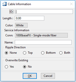
- The Cable Information dialog box opens.
- Key in the Cable ID and length.
- From the Color pull-down menu, select the cable color.
- From the Conn pull-down menu, select the connection type to use.
- Enter the Service Name.
- Choose the Ripple Direction method and if the Service Name should overwrite an existing one encountered while rippling.
- Click OK to save the information.

Remove a Connection
- From the Port Connections dialog box, highlight a connection in the Connections list.
- Click Disconnect.
- The connection is removed from the Connections list.
Edit a Connection
- From the Port Connections dialog box, highlight a connection in the Connections list.
- Click Edit cable.
- The Cable Information dialog box opens.
- Edit the field(s) requiring change and click OK to save and exit.
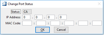
Change Port Status
- From the Port Connections dialog box, highlight a connection in the Connections list.
- Click Port Status.
- The Change Port Status opens.
- Make the necessary change and click OK to save and exit.
View the Connection Report
- From the Port Connections dialog box, highlight a connection in the Connections list.
- Click Terminate.
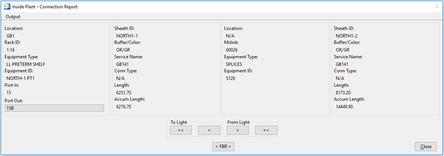
- The Inside Plant - Connection Report opens.
- Click the <<, <, >, or >> buttons to view the different connections on the service path.
- Click <FBR> to view the optical node connection.
- Select Output > Text File to generate a connection report text file.
- Click Close to exit.